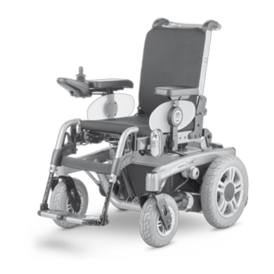
Meyra 1.610 Maintenance And Service Manual

Meyra 1.610 Maintenance And Service Manual

Electric wheelchair
Hide thumbs Also See for 1.610:
Table of Contents

Advertisement

en
Electric wheelchair
Model 1.610 / 1.611 / 1.612 / 1.614 / 1.615
1.616 / 1.617
Maintenance and Service manual
W e
m o v e
p e o p l e .

Advertisement

Table of Contents
loading

Summary of Contents for Meyra 1.610

  • Page 1 Electric wheelchair Model 1.610 / 1.611 / 1.612 / 1.614 / 1.615 1.616 / 1.617 Maintenance and Service manual m o v e p e o p l e .
  • Page 2: Table Of Contents

    Information to maintenance and service work: Working on the vehicle Vehicle identification Term definitions Service position Setting the service position Model 1.617 Overview Model 1.610 Model 1.611 / 1.614 Model 1.612 Model 1.615 Model 1.616 Model 1.617 Safety information Storage...
  • Page 3 Adjusting the seat width through the seat frame Seat depth Adjusting the seat depth through the position of the back support Position of the back support Model 1.610 / 1.611 / 1.612 / 1.615 Model 1.614 Model 1.616 Seat surface Model 1.610 / 1.611 / 1.615...
  • Page 4 Replacing the lighting fixture Replacing the headlight / front turn signal Replacing the back light Batteries Model 1.610 / 1.611 / 1.614 / 1.615 / 1.616 Removing the battery case Inserting the battery case Model 1.612 Removing the battery case Inserting the battery case Model 1.617...
  • Page 5 Adjusting the angle of the back support Replacing the adjustment for angle adjustment Seat inclination (camber), model 1.610 / 1.611 / 1.614 / 1.615 / 1.616 Replacing the adjustment motor for seat inclination Adjusting the front seat height, model 1.610 / 1.611 / 1.615 Adjusting the front seat height, model 1.614...
  • Page 6 Adjustment of seat inclination Mechanical seat inclination adjustments Seat inclination (camber), model 1.610 / 1.611 / 1.614 / 1.615 / 1.616 Replacing the telescopic tube of the seat inclination Adjusting the front seat height, model 1.610 / 1.611 / 1.615 Adjusting the front seat height, model 1.614...
  • Page 7: General

    All required documents as well as additional infor- are assigned to work on the wheelchair. mation to our products are located on our website under: Customer support < www.meyra.com >. Technical questions will gladly be answered by your national Meyra distribution partner.
  • Page 8: Information To Maintenance And Service Work

    Working on the vehicle Information to maintenance and ser- vice work: ☞ For maintenance and repairs the vehicle is to be switched off and secured against uninten- ☞ Every wheelchair should undergo inspection tionally rolling away. once a year. ☞ Additionally the main-/battery fuse is to be re- The inspection increases the safety and extends moved.
  • Page 9: Vehicle Identification

    VEHICLE IDENTIFICATION For a definite vehicle identification in case you have questions, or for spare parts orders, the following data can be read off of the type plate: ☞ view sample-type plate [1] The model description (in the field Type resp. Typ) 2.
  • Page 10: Setting The Service Position

    Setting the service position Model 1.617 In order to be able to adjust the service position [1] unscrew the seat locking device (2) on both sides. Attention! Unintentional lowering of the seat unit! Jamming the fingers, hands and arms are possible. Remove the leg supports before adjusting the service position.
  • Page 11: Model 1.610

    OVERVIEW Model 1.610 Model 1.611 / 1.614 Model 1.612...
  • Page 12: Model 1.615

    Model 1.615 Model 1.616 Model 1.617...
  • Page 13: Safety Information

    SAFETY INFORMATION REQUIRED TOOLS AND AIDS ☞ Wear suitable clothing during service-jobs as For adjustments and maintenance we recommend well as gloves and protective glasses when re- the use of high quality tools. quired. ☞ High quality tools can prevent for example Danger of injuries caused by inappropriate work damages to the surface of the frame as well as clothes.
  • Page 14: Adaptation And Adjustment Jobs

    ADAPTATION AND ADJUSTMENT JOBS The following chapters describe the fitting of the wheel- chair to the changing individual demands of the user. LEG SUPPORT Mechanical leg support Adjusting the height of the footplate Remove the clamping screw (1) to adjust the height. Telescope the footplate to the desired height and then se- cure it with the clamping screw (1).
  • Page 15: Adjusting The Angle Of The Footboard

    Adjusting the angle of the footboard Swivel the footboard down in order to adjust the angle of the footboard [1]. Afterwards loosen the screws (2) on both sides. Tilt the footplate to the desired angle and retighten the screws (2) on both sides. Depth adjustment of the footboard The depth adjustment of the footboard is done by reposi- tioning the removable distancer pieces (3).
  • Page 16: Depth Adjustment Of The Leg Supports

    Depth adjustment of the leg supports Depth adjustment of the leg supports is achieved by reposi- tioning the respective leg support receptacle (1). For depth adjustment of the leg supports loosen the re- spective clamping screws (2). ☞ The headlight is also secured with the clamping screws.
  • Page 17: Leg Support Receptacle

    Leg support receptacle For external seat systems the leg support receptacles (1) are to be adjusted to the amended seat height. Adjusting the leg support receptacle to the thigh length To reposition the leg support receptacle (1) into one of the other two screw positions, both screws (2) need to be re- moved.
  • Page 18: Central Leg Support

    Central leg support Adjusting the height of the footplate Remove the clamping screw (1) to adjust the height. Telescope the footplate to the desired height and then se- cure it with the clamping screw (1). Angle adjustment of the central leg support Remove the screw (2) for angle adjustment of the central leg supports.
  • Page 19: Model 1.617

    Model 1.617 Adjusting the height of the footboard Remove the cover (1) (velcro fastener). Remove the clamping screws (2) to adjust the height. Telescope the footboard to the desired height and then se- cure it with the clamping screws (2). Angle adjustment of the central leg support Screw the two locking screws (3) in or out, for angle adjust- ment of the central leg support.
  • Page 20: Arm Supports

    ARM SUPPORTS Adjusting the height of the arm supports To adjust the height of the arm support, loosen the clamp- ing screw (1), hold the arm support in the desired height and retighten the clamping screw (1). ☞ Adjustment possibilities are reduced in combination with lighted clothes guard plates.
  • Page 21: Depth Adjustment Of The Arm Support Pad

    Depth adjustment of the arm support pad In order to adjust the support surface of the arm support pad, e. g. after changing the seat depth, the attachment screws (1) are to be dismantled. Adjusting the clothes guard Loosen the clamping screws (2) to adjust the height of the clothes guard.
  • Page 22: Lighted Clothes Guard Plates

    LIGHTED CLOTHES GUARD PLATES Refitting the lighted clothes guard plates The following is required for refitting: 1x set lighted clothes guard plates with arm supports 2x receptacle tube 1x Y-cable Assembly Switch the electric wheelchair off and pull the mains fuse.
  • Page 23: Back Support

    BACK SUPPORT Mounting the push bar The single push handles [1] can be replaced by the push bar [2]. Therefore unscrew the screw (3) at both sides. Mounting the stabiliser rod The stabiliser rod (4) can be mounted to the two attach- ment points (5) of the back tubes.
  • Page 24: Secure Positions Of The Back Support

    Adjusted seat inclination: ...............6° The pressure bolt of the back support may only be in posi- tions c, d, or e when driving on hills/slopes. Model 1.610 / 1.611 / 1.614 / 1.615 Seat incli- safe position of the back support...
  • Page 25: Back Support Upholstery

    Back support upholstery After opening the velcro fastener the back support cushion [1] can be taken out of the back support shell. Limit switch ☞ (not with model 1.617 / 1.616) The limit switch (2) prevents exceeding the back support angle in combination with the electric angle adjustment of the back support and electric camber of the seat unit.
  • Page 26: Head Support

    HEAD SUPPORT The head support [1] is swivel proof, height and depth ad- justable as well as removable. ☞ Note: We recommend the fitting of two rear-view mirrors for driving with a head support. Height adjustment and removal of the head support The head support can be detached or adjusted in height after the clamping screw (2) has been slackened.
  • Page 27: Seat Width

    ☞ The application can be viewed in the following table. Table: Arm support receptacle [3] Model Code Arm support receptacle short medium long X 3) X 3) 1.610 4960 X 3) X 3) 5) X 5) X 3) 5) X 5) 1.611 4960 X 3) 5)
  • Page 28: Adjusting The Seat Width Through The Seat Frame

    ☞ The assembly positions can be viewed in the following tables. ☞ On models 1.610 / 1.611 / 1.615 the adjustment tube (5) is no longer required for seat width 38 cm. Table: Assembly position of the cross braces (3)+(4) for model 1.616...
  • Page 29 Table: Assembly position front crossbrace (3) Seat width [cm] Model 1.610 – 1.611 / 1.615 – 1.612 – 1.614 – – 1.617 – Table: Assembly position rear crossbrace (4) Seat width [cm] Model A (with 1.610 A (w/o pos.5) –...
  • Page 30: Seat Depth

    Adjusting the seat depth through the posi- tion of the back support Position of the back support Model 1.610 / 1.611 / 1.612 / 1.615 The seat depth can be adjusted by repositioning the back support. After removing the three attachment screws on both sides, the back support, depending on version strap or shell, can be positioned according to table <...
  • Page 31: Model 1.610 / 1.611 / 1.612

    Position of the back support Model 1.614 The seat depth can be adjusted by repositioning the back support. After removing the three attachment screws on both sides, the back support can be positioned according to table < Seat depth – position of the back support >. Table: Seat depth –...
  • Page 32: Seat Surface

    SEAT SURFACE Model 1.610 / 1.611 / 1.615 By turning the cross brace bracket vertically by 180° and horizontally turning the front cross brace (1) by 180° you can switch from seat plate to seat strap. Position of the cross brace bracket for the...
  • Page 33: Wheels

    WHEELS Wheel change Before starting the disassembly work, support the frame to prevent the wheelchair from tipping over and secure it to prevent an unwanted movement or tipping over. ☞ Always change tyres in pairs. Attention: Never loosen the connection screws of the rim halves (1) to disassemble the wheel.
  • Page 34: Changing The Tyres

    Changing the tyres Disassembly of the tyres Disassemble the wheel. 2. Completely deflate the tyre. Attention: Never loosen the rim half connection screws (1) in order to disassemble the tyre before previously completely deflating the tyre! ☞ Danger of injury! 3.
  • Page 35: Steering Wheels

    Steering wheels Depending on the size of the steering wheel the screwed connection (1) of the support castor and the lower screwed connection (2) of the spring are mounted according to the following table. ☞ (not with model 1.617) Steering wheel Position of the Position of the support castor...
  • Page 36: Fuses

    FUSES Main fuse The main-/battery fuse is switched in line between the two batteries and is inserted in the top left of the fuse holder of the battery case (1). The main fuse holder (2) is located inside the battery box at the back.
  • Page 37: Lighting- / Adjustment Module R-Net

    Lighting- / adjustment module R-Net All electric adjustments are secured electronically through the adjustment module (1) as well as the combined light- ing-/adjustment module. The corresponding adjustment module is, depending on model, either mounted beside the power module [2] or at the rear left, underneath the seat plate [3].
  • Page 38: Lighting

    LIGHTING The lighting (1)+(2) is equipped with longlife LED-technol- ogy. ☞ Note: If a turn-signal is defective, the remaining one blinks at double frequency. Attention: It is to be observed that the cables are not damaged or bent when being placed. ☞...
  • Page 39: Adjusting The Headlights

    Replacing the headlight / front turn signal Model 1.610 / 1.611 / 1.612 / 1.614 / 1.615 / 1.616: In order to replace the headlight / front turn signal, first disconnect the electric and loosen the cable clips, then re- move the attachment screw (1).
  • Page 40 Model 1.617: Remove the cover plate on the side (1). 2. Remove the cable ties. 3. Disconnect the electric connector (2) of the defective bulb. 4. remove the screws for the driving headlights (3) resp the attachment screws of the front turn signals (4). 5.
  • Page 41: Replacing The Back Light

    Replacing the back light Model 1.610 / 1.611 / 1.614 / 1.615 / 1.616: In order to replace the back light (1) first disconnect the electric. 2. Afterwards press down the to springs at the side (2) and take out the back light.
  • Page 42 Model 1.617: Remove the cover plate on the side (1). 2. Remove the cable ties. 3. Disconnect the electric connector (2) of the defective bulb. 4. Screw off the attachment plate (3) of the rear lighting. 5. Replace the defective bulb [4]. 6.
  • Page 43: Batteries

    BATTERIES After lifting out the battery case the batteries can be re- placed. Model 1.610 / 1.611 / 1.614 / 1.615 / 1.616 Removing the battery case Remove the attachment screws (1). 2. Lift the battery case slightly over the rear grip edge and pull it out towards the back [2].
  • Page 44: Model 1.612

    Model 1.612 Removing the battery case Remove the attachment screws (1). 2. Lift the lid off of the battery case [2]. 3. Pull the battery connection plug (3) from the power module. 4. Lift the battery case slightly over the rear grip edge and pull it out towards the back [4].
  • Page 45: Model 1.617

    Model 1.617 Removing the batteries Unscrew the attachment screws (1) of the rear cover. 2. Fold the rear cover open and place it to the side [2]. 3. Pull the battery connection plug (3) from the power module. 4. Set into service position [4]. ☞...
  • Page 46: Battery Charger

    BATTERY CHARGER ☞ Note: ☞ When changing to batteries with considerably different capacity also use a corresponding charger, so that the charging periods remain limited and the batteries are charged completely. ☞ When replacing the secondary plug [B] (part-no. 206 917 100) a bridge (4), view inside view of the plug, must be welded between the contacts 2 (earth) and 3.
  • Page 47: Drive

    The replacement of the left drive is to be done accordingly in the same fashion. Remove the battery case. ☞ Model 1.610 / 1.611 / 1.614 / 1.615 / 1.616 [4] ☞ Model 1.612 [5] 2. Unscrew the drive wheel [6].
  • Page 48: Model 1.610 / 1.611 / 1.614 / 1.615 / 1.616

    Model 1.610 / 1.611 / 1.614 / 1.615 / 1.616 Pull the motor connector plug leaving the drive (1) off of the power module. 2. Pull the wheel flange (2) [3]. ☞ For this disassemble the screws (4). ☞ An extractor might be required for this.
  • Page 49: Model 1.612

    Model 1.612 Pull the motor connector plug leaving the drive (1) off of the power module. 2. Pull the wheel flange (2) [3]. ☞ For this disassemble the screws (4). ☞ An extractor might be required for this [5]. 3. Remove the drive toward the bottom [6]. ☞...
  • Page 50: Model 1.617

    Model 1.617 Pull the motor connector plug leaving the drive (1) off of the power module. 2. Pull the wheel flange (2). ☞ For this disassemble the screws (3). ☞ An extractor might be required for this. 3. Remove the splash guard and drive [5]. ☞...
  • Page 51: Carbon Brushes

    Carbon brushes The carbon brushes (1) are supplied as a set and are to be replaced as a set. ☞ Note: ☞ Do not touch the friction surface of the carbon brushes! ☞ The carbon brushes are worn when they are used up to 8 mm length.
  • Page 52: Vehicle Suspension

    VEHICLE SUSPENSION Suspension of the chassis For optimal sitting comfort the suspension (1) can be adjust- ed according to the desire of the user. Attention: Make sure that the adjustment ring sits securely before starting to drive. ☞ Screw a loose adjustment ring (2) tight enough, un- til the pressure of the spring prevents further loos- ening.
  • Page 53: Replacing The Spring

    ☞ For this observe chapter Steering wheels on page 35. Attention: The spring might be under extreme pressure. Model 1.610 / 1.611 / 1.615 / 1.614 Remove the screws (1) to replace the spring. Model 1.612 For replacement of both springs for the front rocker the screws (2) on both sides are to be removed.
  • Page 54: Usb Connector Socket

    USB CONNECTOR SOCKET The USB-connection socket [1] is maintenance free. Assembly Assembly of the USB-connection socket is dome with the help of an angle bracket that can be positioned individually on the seat frame tube of the electric wheelchair [2]. ☞...
  • Page 55: Electronic Modules

    ELECTRONIC MODULES Power modules The power module < R-Net >[1] resp. VR2 [2] stores the set- tings of the driving parameters and adopts as the power electronic the addressing of the drive motor respectively on two motor wheelchairs the addressing of both drive motors. The inlets and outlets of the power module are short circuit proof, so that the lead fuse is not applicable.
  • Page 56: Standard Setting Of The Vr2 Driving Parameters

    Standard setting of the VR2 driving parameters The parameter values in the following tables are selected so that the inspection requirements of the CE certification are fulfilled. Standard setting of the VR2 driving parameters up to 6 km/h Number of Drive Profiles Acceleration (Acceleration speed forward) Deceleration...
  • Page 57: Standard Setting Of The R-Net Driving Parameters, Profile 1, 2, 8 W/O Stability Sensor (Esp)

    Profile Universal Omni Accompanying person Standard setting of the R-Net-driving parameter up to 6 km/h (only model 1.610 / 1.611 / 1.612 / 1.615 / 1.616) w/o stability sensor (ESP) Number of enable Drive Profiles maximum / minimum Forward Speed [%]...
  • Page 58 Standard setting of the R-Net-driving parameter up to 6 km/h (only model 1.614) w/o stability sensor (ESP) Number of enable Drive Profiles maximum / minimum Forward Speed [%] 95 / 15 95 / 15 95 / 15 Reverse Speed [%] 30 / 10 30 / 10 30 / 10...
  • Page 59 Standard setting of the R-Net-driving parameter up to 6 km/h (only model 1.617) w/o stability sensor (ESP) Number of enable Drive Profiles maximum / minimum Forward Speed [%] 50 / 10 50 / 10 50 / 10 Reverse Speed [%] 30 / 5 30 / 5 30 / 5...
  • Page 60 Standard setting of the R-Net-driving parameter up to 10 km/h (only model 1.611 / 1.612 / 1.616) w/o stability sensor (ESP) Number of enable Drive Profiles maximum / minimum Forward Speed [%] 95 / 10 95 / 10 95 / 10 Reverse Speed [%] 20 / 10 20 / 10...
  • Page 61 Standard setting of the R-Net-driving parameter up to 10 km/h (only model 1.614) w/o stability sensor (ESP) Number of enable Drive Profiles maximum / minimum Forward Speed [%] 95 / 10 95 / 10 95 / 10 Reverse Speed [%] 20 / 10 20 / 10 20 / 10...
  • Page 62 Standard setting of the R-Net-driving parameter up to 13 km/h (only model 1.615) w/o stability sensor (ESP) Number of enable Drive Profiles maximum / minimum Forward Speed [%] 100 / 10 100 / 10 46 / 10 Reverse Speed [%] 20 / 10 20 / 10 20 / 10...
  • Page 63 Standard setting of the R-Net-driving parameter up to 10 km/h (only model 1.617) w/o stability sensor (ESP) Number of enable Drive Profiles maximum / minimum Forward Speed [%] 80 / 10 80 / 10 80 / 10 Reverse Speed [%] 30 / 5 30 / 5 30 / 5...
  • Page 64: Standard Setting Of The R-Net Driving Parameters, Profile 1, 2, 3, 8 With Stability Sensor (Esp)

    Universal Omni ESP-Sensor off Accompanying person Standard setting of the R-Net-driving parameter up to 6 km/h (only model 1.610 / 1.611 / 1.612 / 1.615 / 1.616) with stability sensor (ESP) Number of enable Drive Profiles maximum / minimum Forward Speed [%]...
  • Page 65 Standard setting of the R-Net-driving parameter up to 10 km/h (only model 1.610 / 1.611 / 1.612 / 1.616) with stability sensor (ESP) Number of enable Drive Profiles maximum / minimum Forward Speed [%] 95 / 10 95 / 10...
  • Page 66 Standard setting of the R-Net-driving parameter up to 13 km/h (only model 1.615) with stability sensor (ESP) Number of enable Drive Profiles maximum / minimum Forward Speed [%] 100 / 10 100 / 10 100 / 10 46 / 10 Reverse Speed [%] 20 / 10 20 / 10...
  • Page 67: Power Module, Replacing The Lighting, Resp. Lighting/Adjustment Module

    ☞ Then carry out a function test. ☞ Therefore observe chapter Functional checks on page 94. Power module 1.610 / 1.611 / 1.614 / 1.615 / 1.616 The power module (1) is mounted according to the hole or- der onto the frame plate [2].
  • Page 68: Lighting- / Adjustment Module R-Net

    < Inhibit 4 > [6] of the new module. The adjustment module is mounted, depending on model, as follows: Model 1.610 / 1.611 / 1.614 / 1.615 beside the power module [2]. Model 1.612 / 1.616 on the left underneath the seat plate [4], with two screws (3).
  • Page 69: Plug Allocation Of The Lighting/Adjustment Module R-Net

    The lighting module VR2 (6) is used in combination with the operating module VR2 and mounted beside the power module onto the frame plate (model 1.610 / 1.611 / 1.615 / 1.616) [7] resp. fastened onto the power module with velcro straps (model 1.612).
  • Page 70: Electronic Driving Stability Sensor (Esp)

    Electronic driving stability sensor (ESP) The driving stability sensor (ESP) is attached to the front right onto the main frame with angled mounting plates [1] ☞ Retrospective fitting of the electric wheelchair with a driving stability sensor may only be carried out at our site! Replacing the driving stability sensor Pull the connector cable of the driving stability sensor.
  • Page 71: Electrical Adjustments

    ELECTRICAL ADJUSTMENTS Adjusting the angle of the back support Replacing the adjustment for angle adjustment Pull the connection plug of the adjustment motor (1) for angle adjustment out of the adjustment module un- derneath the seat plate [2]. 2. Remove the tube folding plug (3) and screw (4) for at- tachment of the adjustment motor for angle adjust- ment.
  • Page 72: Seat Inclination (Camber), Model 1.610 / 1.611 / 1.614 / 1.615

    Seat inclination (camber), model 1.610 / 1.611 / 1.614 / 1.615 / 1.616 Replacing the adjustment motor for seat inclination Pull the connection plug of the corresponding adjust- ment motor for seat inclination [1] out of the adjust- ment module and guide it to the front.
  • Page 73: Adjusting The Front Seat Height, Model 1.610 / 1.611

    Adjusting the front seat height, model  1.610 / 1.611 / 1.615 The front seat height can be determined from table < Front seat height >, depending on the size of the steering wheel, position of the horizontal beam [2] and rear seat frame po- sition [3].
  • Page 74: Adjusting The Front Seat Height, Model 1.614

    Adjusting the front seat height, model 1.614 The corresponding front seat height can be assigned from table < Front seat height >, depending on the rear seat frame position [2] and the position of the adjustment motor. The bold printed figures for height (in mm) within the table correspond to the manufacturer setting.
  • Page 75: Adjusting The Front Seat Height, Model 1.616

    Adjusting the front seat height, model 1.616 The front seat height can be determined from table < Front seat height >, depending on the size of the steering wheel, the rear seat frame position [2] and the position of the ad- justment motor [3].
  • Page 76: Seat Inclination (Camber), Model 1.612

    Seat inclination (camber), model 1.612 Replacing the adjustment motor for seat inclination Drive the lifting rod into the highest position in order to re- place the adjustment module (1) for seat inclination. Pull the connection plug of the respective adjustment motor (1) out of the adjustment module underneath the seat plate [2] and guide it forward.
  • Page 77: Seat Inclination (Camber), Model 1.617

    Seat inclination (camber), model 1.617 Replacing the adjustment motor for seat inclination Drive the seat into the highest position in order to replace the adjustment module (1) for seat inclination. Pull the connection plug of the corresponding adjust- ment motor (1) off of the adjustment module [2]. 2.
  • Page 78: Seat Height, Model 1.617

    Seat height, model 1.617 Replacing the adjustment motor for seat height Drive the seat into the highest position and secure it in place in order to replace the adjustment module (1) for seat height. Pull the connection plug of the corresponding adjust- ment motor (1) off of the adjustment module [2].
  • Page 79: Lifting Rod, Model 1.612

    Lifting rod, model 1.612 For disassembly of the seat unit it is recommended to take off all removable parts [1] Removing the lifting rod For removal, drive the lifting rod and inclination into the re- spective highest position [1]. Pull the connection plug of the adjustment module (2) off of the power module.
  • Page 80: Mounting The Lifting Rod

    ☞ In doing so watch for cables that might still be at- tached. – If required, remove corresponding cable binders. 6. Remove the four lower screws of the lifting rod. ☞ While doing so have someone help you secure the actuator against unwanted tilting.
  • Page 81: Seat Height, Model 1.612

    Seat height, model 1.612 Adjustment of the seat height Lifting rod with electric inclination To adjust the seat height the attachment plate (1) is to be positioned as follows: Seat height 45 cm The attachment plate (1) is mounted to the lowest attach- ment hole (2) [3].
  • Page 82 Seat height 48 cm The attachment plate (1) is mounted to the topmost attach- ment hole (4) [5]+[6].
  • Page 83 Seat height 51 cm For this the attachment plate (1) is mounted turned vertical- ly by 180° to the attachment holes (2) [7]+[8].
  • Page 84: Lifting Rod Without Electric Inclination

    Lifting rod without electric inclination To adjust the seat height the attachment plate (1) is to be positioned as follows: Seat height 45 cm The attachment plate (1) is mounted to the topmost attach- ment hole (2) [3]. Seat height 48 cm The attachment plate (1) is mounted to the lowest attach- ment hole (4) [5].
  • Page 85: Mechanical Seat Inclination Adjustments

    MECHANICAL SEAT INCLINATION ADJUSTMENTS Seat inclination (camber), model 1.610 / 1.611 / 1.614 / 1.615 / 1.616 Replacing the telescopic tube of the seat inclination To replace the telescopic tube of the seat inclination [1] remove the lower bolt (2) and the upper spring bolt/tube folding plug (3).
  • Page 86: Adjusting The Front Seat Height, Model 1.610 / 1.611

    Adjusting the front seat height, model  1.610 / 1.611 / 1.615 In order to adjust the front seat height the corresponding screw (Z) needs to be removed. = (1) = (2) The hole in the telescopic tube [1] (column Pos.) for the = (3) screw [Z] can be determined from the table <...
  • Page 87: Adjusting The Front Seat Height, Model 1.614

    Adjusting the front seat height, model 1.614 In order to adjust the front seat height the corresponding screw (Z) needs to be removed. = (1) = (2) The hole in the telescopic tube [1] (column Pos.) for the = (3) screw [Z] can be determined from the table < Front seat (1) / = (4) height >, depending on the steering wheel size, the rear seat (2) / = (5)
  • Page 88: Adjusting The Front Seat Height, Model 1.616

    Adjusting the front seat height, model 1.616 In order to adjust the front seat height the corresponding screw (Z) needs to be removed. = (1) The hole in the telescopic tube [1] (column Pos.) for the = (2) screw [Z] can be determined from the table < Front seat = (3) height >, depending on the steering wheel size, the rear seat (1) / = (4)
  • Page 89: Error Indication

    ERROR INDICATION Error indication R-Net LCD-Display Errors will be shown in the LCD-display (15) of the operating module in the following error code. (a) Shows the cause of the error. (b) Shows the error code. Error-Code Cause of error 1E01 The battery charger is still connected.
  • Page 90: R-Net Led And Vr2

    (2), (3) indicate the possible cause of the malfunction. ☞ Therefore observe table < Error diagnostics >. ☞ Note: If the malfunction cannot be repaired and the vehicle no longer operated, contact your national Meyra-Orto- pedia sales partner. Error diagnostics Cause of error Fault correction The battery voltage is too low.
  • Page 91 Cause of error Fault correction A system or joystick error. Operating- or power module defective. Movement of the joystick during ignition, resp. during the test phase of the operating module can also lead to this error indication. Defective power module or a system Check cables and connecting plugs.
  • Page 92: Information Illustration Through The Battery Gauge

    Information illustration through the battery gauge For information illustration the light segments of the battery gauge (1) blink slowly. The number of blinking segments in- dicates the type of information. Information Cause Remedy Running lights up/ Joystick moved too early. Release the joystick, switch off the operat- down ing module and switch it back on.
  • Page 93: Information Illustration Through The Display Of The Speed Preselection

    Information illustration through the display of the speed preselection For information illustration the light segments of the display for the speed preselection (1) blink. Information Cause Remedy Running lights up/ The anti-theft function is activat- Switch off the anti-theft function. down ☞...
  • Page 94: Functional Checks

    FUNCTIONAL CHECKS Braking distance When programming the delay value observe the maximum value of the braking distance of EN 12184. Checking the cable layout After replacing defective parts and during mainte- Maximum braking distance of EN 12184 nance always check the correct cable layout. Speed max.
  • Page 95: Maintenance

    m o v e p e o p l e . MAINTENANCE Before reimplementation the wheelchair is to un- dergo a complete inspection. Wheelchairs are medical devices of the class I-MDD. ☞ The hygienic measures required for reinstall- As a medical device they underlie the operator ment are to be carried out in correspondence provision and are to be maintained regularly.
  • Page 96: Maintenance Checklist Of The Annual Maintenance Jobs

    Maintenance checklist of the annual maintenance jobs Preparation for visual check Removed seat and back support elements, leg supports, arm support units. If necessary, clean the ❑ vehicle or the modules before the visual check. Visual check coachwork Checked the frame, add-on components and accessories for damage, corrosion and damaged ❑...
  • Page 97 Maintenance checklist of the annual maintenance jobs Batteries No dirt or outer damage to the batteries. ❑ ❑ Checked the screwed connections of the battery poles. Poles and attachment clamps are clean and greased with Vaseline or Acid protector grease. ❑...
  • Page 98: Din Norms And Guidelines

    Maintenance checklist of the annual maintenance jobs Brakes Checked the function of the brakes. ❑ ❑ The maximum braking distance corresponds to EN 12184. Oil/Grease Checked turning points and bearing areas of operating levers and moveable parts for easy function- ❑...
  • Page 101: Notes

    NOTES...
  • Page 102 NOTES...
  • Page 103 NOTES...
  • Page 104 Your specialist dealer MEYRA GmbH Meyra-Ring 2 D-32689 Kalletal-Kalldorf +49 5733 922 - 311 +49 5733 922 - 9311 info@meyra.de www.meyra.de MEYRA 205 338 901 (Status: 2015-04) All technical modifications reserved. Original Maintenance and Service manual.

This manual is also suitable for:

1.6111.6121.6141.6161.6171.615

Table of Contents