Table of Contents
Advertisement
Quick Links
Advertisement
Table of Contents

Related Manuals for Meyra 1.618


Summary of Contents for Meyra 1.618
- Page 1 Electric wheelchair Model 1.618 Operating manual...
-
Page 2: Table Of Contents
Indications / contraindications Acceptance Intended purpose Adjustment Combination with manufacturer foreign products Reinstallment Life span Base position Overview Model 1.618 Handling the electric wheelchair Securing the electric wheelchair Functional checks Driving Brakes Service brake Braking the wheelchair Emergency braking Parking brake... - Page 3 Selecting the operation Pre-operation checks Battery charging procedure Positioning the operating module Function description Adjusting the distance to the padded arm support Removing the operating module Inserting the operating module Swivelling the operating module Height adjustment of the operating module Leg supports Central leg support Calf belt...
- Page 4 Back support Folding down the back support Unfolding the back support Adjusting the back support angle Secure positions of the back support Adjustable back Removing the back support upholstery Placing the back support upholstery Electrically adjustable back support Folding down the electrically adjustable back support Unfolding the back support Back support upholstery Tilt switch (optional)
- Page 5 Loading and transportation Loading Ramps and lifting platforms Transport of people inside a motor vehicle Transport security Tyres Maintenance Maintenance Maintenance schedule Fuses Replacing the fuses Lighting Headlights Fault correction Basic safety information Accompanying person Transfer out of the electric wheelchair Reaching for objects Driving on falling, rising or transverse gradients Crossing obstacles...
- Page 6 Tyre pressure of pneumatic tyres Maximum range Hill climbing ability Applied norms Values acc. to ISO 7176-15 for model 1.618 Further technical data for model 1.618 Meaning of the labels on the electric wheelchair Meaning of the symbols on the type plate Meaning of the symbols on the washing instruction Inspection certificate...
-
Page 7: Meaning Of The Applied Markers
< Information center > on our website: Safety instructions with a coloured back- < www.meyra.com >. ground are mandatory and need to be observed under any circumstance! We have developed an electric wheelchair that complies with the technical and gov- ☞... -
Page 8: Acceptance
ACCEPTANCE – other diseases. Also to be observed for individual provision All products are checked for faults in the are the physical and psychological state, factory and packed in special boxes. age of the handicapped person as well as ☞ However, we request that you check the personal living condition and private the electric wheelchair for possible environment. -
Page 9: Adjustment
The electric wheelchair offers manifold ad- ☞ We recommend a regular inspection of justment possibilities to individual vital sta- the electronic wheelchair adjustment tistics. in order to ensure a long-term optimal provision even with changing illness/ National regulations might prevent the use handicap patterns of the user. -
Page 10: Life Span
LIFE SPAN We expect an average life span of about 5 years for this product, as far as the product is applied for its designated purpose and all maintenance and service guidelines. The life span of your product depends upon the fre- quency of use, the application environment and care. -
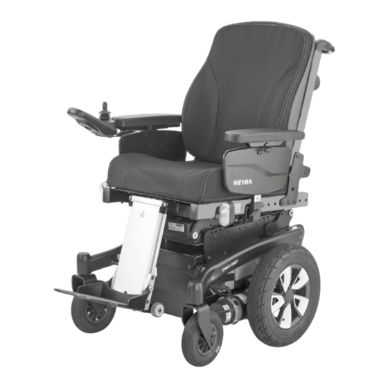
Page 11: Overview
OVERVIEW Model 1.618 The overview shows the most important components and operating devices of the electric wheelchair. Pos. Description (1) Head support (2) Back support (3) Arm support (4) Seat cushion (5) Steering wheel fork (6) Footplate (7) Steering wheel... -
Page 12: Handling The Electric Wheelchair
HANDLING THE ELECTRIC BRAKES WHEELCHAIR Brake the electric wheelchair down care- fully and in time. This is especially the case Securing the electric wheelchair when driving in front of people and while driving downhill! The electric wheelchair is to be secured as follows to prevent it from rolling off... -
Page 13: Locking The Brakes
Locking the brakes It should not be possible to push the elec- tric wheelchair forward when the brakes are engaged. To engage the brakes swivel the selection lever drive-/push mode on both sides as far as possible into drive mode [1]. ☞... -
Page 14: Drive-/Push Mode
Drive-/push mode Only switch the electric wheelchair to push mode when it is standing still for positioning or in case of emergencies, but not on slopes/hills. ☞ The electric magnetic brakes are switched off in the push mode. – A braking of the electric wheelchair is then only possible by switching to the drive mode. -
Page 15: Selecting The Operation
SELECTING THE OPERATION In order to obtain operational readiness of the electric wheelchair the following direc- tions are to be carried out in the indicated order. ☞ Charge the drive batteries via the oper- ating module before the first journey. Selecting the motor mode. - Page 16 Check the position of the operating module. The maximum extension reached, when a mark becomes visible in the receptacle tube of the operating module. ☞ The operating module should be positioned in such a way that you can comfortably and safely steer the electric wheelchair.
-
Page 17: Pre-Operation Checks
Pre-operation checks Before starting to drive, the following should be checked: ☞ the battery charging condition. ☞ The setting of the preselected final speed. – For this observe the operating man- ual < Operating module >. Battery charging procedure Do not insert any objects other than the battery charger plug into the battery charging socket. -
Page 18: Positioning The Operating Module
Positioning the operating module Switch off the operating module before adjusting/removing it. Function description You will find a detailed description of the keys and symbols in the operating manual for < Operating module >. The position of the operating module can be adjusted to suit the individual size of the user. -
Page 19: Swivelling The Operating Module
Swivelling the operating module Do not grab into the area of the cross brace. – Danger of squashing! With the swivel away operating module adapter [1] the operating module can be swivelled back to the side (2) so that it is located parallel to the arm support. -
Page 20: Leg Supports
LEG SUPPORTS Before any actions on the leg support the electric wheelchair is to be secured against unintentional rolling motions. ☞ Therefore observe chapter Securing the electric wheelchair on page 12. Central leg support The footboard [1] can be folded upward [2] in order to ease entry or exiting of the user. -
Page 21: Calf Belt
Calf belt Do not drive without the calf belt. – Dan- ger of accident! The removable calf belt (1) prevents the feet from sliding off the back of the footplates. ☞ The calf belt must be removed in order to swivel away the leg supports. ☞... -
Page 22: Lower Leg Support
Lower leg support The footplates, resp. footboard needs to be folded up before entry or exit [1] / [2]. ☞ Check the locking points! – Remove both feet from the footplates. – Remove the calf belt (3), if present. ☞ Therefore observe chapter Calf belt on page 21. -
Page 23: Leg Support Upper Part
Leg support upper part The upper leg support with an inserted lower leg support is termed leg support. Turning the leg supports to the side Leg supports turned to the side are re- leased automatically and can easily come off. For easy transfer out of/into the electric wheelchair as well as driving closer to a clos- et, bed or bathtub the leg supports can be... -
Page 24: Swivelling In The Leg Supports
Swivelling in the leg supports For inward swivelling, let the leg supports swivel forward until the lock audibly engag- es [1]. ☞ After audibly swivelling the leg sup- ports inward check the respective lock- ing device. ☞ Afterwards observe chapter Lower leg support on page 22. -
Page 25: Removing The Leg Supports
Removing the leg supports For easy transfer into and out of the electric wheelchair as well as a reduced wheelchair length (important for transport) the leg sup- ports can be removed [1]. ☞ Remove the calf belt before swivelling away the leg supports. ☞... -
Page 26: Mechanically Height-Adjustable Leg Supports
Mechanically height-adjustable leg supports Never put the free hand into the adjust- ment mechanism while adjusting the height adjustable leg support. – Danger of jamming! Have the leg support that is to be adjust- ed secured against falling away by an ac- companying person. -
Page 27: Electrically Height-Adjustable Leg Support
Electrically height-adjustable leg support Never put the free hand into the adjust- ment mechanism while adjusting the height adjustable leg support. – Danger of jamming! Electric contact is automatically established when attaching the electrically height ad- justable leg support [1]. Height adjustment For height adjustment, raise or lower the leg support to the desired height via the oper-... -
Page 28: Removing The Electrically Height Adjustable Leg Support
Removing the electrically height adjust- able leg support When the electrically height adjustable leg supports are removed the electric contact (3) needs to be protected from dampness, water and dust or dirt (e. g. for longer storage)! ☞ Possible function error of the electri- cal adjustment. -
Page 29: Arm Supports
ARM SUPPORTS Do not use the arm supports [1] to lift or carry the electric wheelchair. Do not drive without the arm supports! Removing the arm support To remove the arm support, loosen the clamping screw (2) first and then pull out the arm support toward the top . -
Page 30: Back Support
BACK SUPPORT The back support can be folded down for storage or transport. ☞ For better demonstration of the wire cable (1) the back support is shown without cushion. Folding down the back support ☞ If required remove the seat pad (velcro fastener). -
Page 31: Secure Positions Of The Back Support
Model 1.618 Seat inclina- safe position of the back support incli- Adjusted seat inclination tion nation [1] 2°... -
Page 32: Adjustable Back
Adjustable back The adjustable back is adjustable through a velcro strap on the spanning straps (2). Removing the back support upholstery For removal, first pull off the rear part of the back support upholstery (1), then fold it over to the front and pull it off of the adjustable back strap (3). -
Page 33: Electrically Adjustable Back Support
Electrically adjustable back sup- port Any change to the seat inclination will lead to different safe back support adjust- ments! Only adjust the back support when the electric wheelchair is standing on a level surface. A danger of tipping over exists on gradients! The back support [1] is electrically adjusta- ble. -
Page 34: Back Support Upholstery
Back support upholstery The back support upholstery is secured to the back support shell with Velcro fasteners and can be pulled off [1]. Tilt switch (optional) Optionally your electric wheelchair can be equipped with a tilt switch that limits the back support angle in combination with the seat inclination. -
Page 35: Seat
SEAT Seat pad The seat pad [1] is attached to the seat plate with velcro straps and can be removed for cleaning and maintenance. Replace and attach the seat pad again after cleaning or maintenance [1]. – Velcro fasten- Seat cushion The seat cushion is placed with the burling side onto the seat plate. -
Page 36: Seat Height Adjustment
Seat height adjustment Before seat height adjustment, check whether the adjustment area is free of ob- stacles. – Danger of injury! Use of the seat height adjustment is only permitted on straight surfaces and during stillstand of the vehicle. The seat height [1] can be controlled through the operating module. -
Page 37: Head Support
HEAD SUPPORT We recommend the fitting of two rear- view mirrors for driving with a head sup- port. The head support is swivel/proof, height- and depth adjustable as well as removable. Adjustment of the head support The maximum height adjustment is indi- cated by the marking! The head support can be detached or ad- justed in height after the clamping lever (1) -
Page 38: Retaining Strap
RETAINING STRAP Make sure that no objects are trapped between belt and the body! – Thus you avoid painful pressure points. The retrospective assembly of a retaining strap is only to be carried out by a special- ist workshop! The retaining strap is not part of the re- taining system for the electric wheelchair and/or the user during transport in motor vehicles. -
Page 39: Usb Connector Socket
USB CONNECTOR SOCKET The maximum power consumption may not exceed 1 A per connection! ☞ The USB connector socket requires a permanent power supply. This may re- quire a more frequent recharging of the batteries. The USB connector socket serves to con- nect devices with a USB plug type A. -
Page 40: Attendant Control With Priority Switch
ATTENDANT CONTROL WITH PRIORITY SWITCH The control unit for accompanying person enables the accompanying person an easy control of the electric wheelchair with auxil- iary operating module. Positioning the controller ☞ Switch off the operating module before position adjustment! – This prevents an unwanted movement of the electric wheelchair. -
Page 41: Rear-View Mirror
REAR-VIEW MIRROR Removing the rear-view mirror To remove the rear-view mirror loosen the clamping screw (2) and pull the rear-view mirror forward out of the arm support tube. ☞ Carefully place the rear-view mirror down and protect the mirror glass from strain or other objects. -
Page 42: Lighting
LIGHTING For driving outdoors and on public roads the electric wheelchair is equipped with LED-lighting equipment. The lighting is activated over the operating module for the driver. ☞ Therefore observe operation manual < Operating module >. ☞ Always switch on the lighting system in poor visibility conditions and especially during darkness in order to see better and be better seen by others. -
Page 43: Loading And Transportation
The maximum bearing height specified our website < www.meyra.com > in the for the ramp must be greater than the < Download Archive >. height 'h' from the ground to the loading People transportation acc. -
Page 44: Transport Security
The specific document for the an- choring system can also be viewed in the product specific category < Operating man- uals > on our website < www.meyra.com >. Transport security All regulations and directions of the re- spective transport company are to be ob- served. -
Page 45: Tyres
TYRES Tyres are made of a rubber mixture and can leave permanent or difficult-to-remove marks on some surfaces (e.g. plastic, wood- en or parquet flooring, carpets, mats). We cannot accept liabilty for damages on sur- faces caused by wear or chemical processes of the tyres. -
Page 46: Maintenance Schedule
Maintenance schedule WHEN WHAT REMARK Before starting out General Carry out test yourself or with a helper. Test for faultless operation. Checking the magnet- Carry out test yourself or with ic brake a helper. Move the selection lever If the electric wheelchair can for the drive/push mode be pushed, have the brakes into the drive mode posi-... - Page 47 WHEN WHAT REMARK Every 2 months Check tyre profile Carry out a visual check your- (depending dis- self or with a helper. Minimum tread = 1 mm tance covered) If the tyre profile is worn down or if the tyre is damaged, con- sult a specialist workshop for repairs.
-
Page 48: Fuses
Fuses Only replace the safety fuse with a safety fuse of the same type! Replacing the fuses Before replacing fuses, park the electric wheelchair on a level surface and secure it from rolling away. ☞ Therefore observe chapter Securing the electric wheelchair on page 12. -
Page 49: Lighting
Lighting The lighting (1)+(2) is equipped with longlife LED-technology. ☞ Immediately have a defective LED-lamp repaired by a specialist workshop. Headlights The housing of the light (1) must be adjust- ed so that the light cone is visible on the driving surface. -
Page 50: Fault Correction
Fault correction Fault Cause Remedy Battery indicator on the Battery fuse is defective or Replace defective fuse or operating module does not correctly inserted. clean contacts and insert not light up after the correctly. switch-on. Plug connection of the Check the plug connec- power supply without... -
Page 51: Basic Safety Information
Prevent such heating by that can be found on our website: < www. parking the electric wheelchair in a shad- meyra.com >. ed area. Special attachment points for the carry Do not insert fingers into open frame along objects are the push handles. -
Page 52: Transfer Out Of The Electric Wheelchair
Transfer out of the electric wheel- Never switch to push mode on gradients. The automatic brakes are inoperative in the chair push mode. Drive with the electric wheelchair as closely Do not push the vehicle on gradients. as possible to the spot where you want to switch out of the wheelchair. -
Page 53: Crossing Obstacles
Crossing obstacles Electrical system The obstacle crossing capability depends An incorrect and/or inappropriate modifi- on the driving surface gradients, the ad- cation of the driving behaviour can impair justment of the leg supports and other the safety of the electric wheelchair and factors. -
Page 54: Driving On Public Highways
CLEANING wheelchair cannot slide away in case of an accident or sudden braking ma- The plastic panelling is attacked through noeuvre. non-ionic tensides as well as solvents and – Additionally activate the parking brakes. especially alcohol. Do not clean the electric wheelchair with Driving on public highways a high-pressure cleaner! –... -
Page 55: Finish
< Information center > on our website: ☞ During the use of disinfectants it can < www.meyra.com >. happen that surfaces might be affect- ed in such a fashion that the long term Finish functionality of parts can be limited. -
Page 56: Spare Parts
DISPOSAL Spare parts Spare parts can only be ordered from spe- cialist dealers. In case of repair work, only original spare parts are to be used! ☞ Spare parts from other manufacturers can cause malfunctions. The spare parts list with the respective part numbers and drawings is available at the specialist dealer. -
Page 57: Information For The Specialist Dealer
A maintenance and service manual for ming device. this wheelchair is available on our website < www.meyra.com > in the service area ☞ Therefore observe respective < Download >, in which you can find the fol- <... -
Page 58: Technical Data
TECHNICAL DATA Maximum range The nominal values indicated by are reason- All data given in the < Technical data > refers able in compliance with ISO 7176-4. to the standard version. The maximum range depends to a large ex- tent on the following factors: Dimensional tolerance ±15 mm, ±... -
Page 59: Applied Norms
Applied norms The electric wheelchair complies with the norm: – EN 12184: 2014 – ISO 7176-8: 2014 – ISO 7176 -19: 2008 ☞ Assessment of the Crashtest, in which the electric wheelchair is at- tached to the retaining system of the vehicle, has been carried out according to the testing methods of annex D. -
Page 60: Values Acc. To Iso 7176-15 For Model 1.618
Values acc. to ISO 7176-15 for model 1.618 min. max. Overall length (measured at 4° seat inclination) with central leg support 1060 mm 1150 mm with divided leg supports 1180 mm 1250 mm Overall width 12"-wheel / 14"-wheel SW = 380 mm... - Page 61 Values acc. to ISO 7176-15 for model 1.618 min. max. Seat lift, code 27: Seat lift (lifting height) 0 mm 300 mm Seat angle 0° 30° Seat surface height 870 mm (with Ergoseat with extended seat lift) Back support angle, mechanical -10°...
- Page 62 Values acc. to ISO 7176-15 for model 1.618 min. max. Minimal turning radius (measured at 4° seat inclination) with central leg supports 700 mm 800 mm (depending on features) with divided leg supports 800 mm 900 mm (depending on features)
-
Page 63: Further Technical Data For Model 1.618
Further technical data for model 1.618 min. max. Sound level 70 dB(A) Protection class IP X4 Min. turning area central leg support 1050 mm 1150 mm divided leg support 1130 mm 1230 mm Performance drive control with 180 W drives... - Page 64 Further technical data for model 1.618 min. max. Height, with standard- or adjustable back 630 mm 710 mm Height, with ErgoSeat-cushion 700 mm 800 mm (Without arm support, back folded onto seat, seat cushion removed from seat plate and laid onto back)
-
Page 65: Meaning Of The Labels On The Electric Wheelchair
Meaning of the labels on the electric wheelchair Attention! Read the operating manuals and other provided documen- tation. Do not lift the electric wheelchair at the arm supports or leg supports. Removable parts are not suitable for carrying. Drive mode Push mode Push only on level surfaces. -
Page 66: Meaning Of The Symbols On The Type Plate
Meaning of the symbols on the type plate Manufacturer Order number Serial number Production date Permitted user weight max. permissible total weight Permitted axle weights Max. permissible rising gradient Max. permissible falling gradient Permitted maximum speed The product is approved as a seat within a motor vehicle. Max. -
Page 67: Meaning Of The Symbols On The Washing Instruction
Meaning of the symbols on the washing instruction (the symbols correspond to European standard) Wash as delicates with the indicated maximum temperature in °C. Wash as regular laundry with the indicated maximum temperature in °C. Hand wash only Do not bleach. Not suited for the dryer. -
Page 68: Inspection Certificate
INSPECTION CERTIFICATE Recommended safety inspection 1st year (at least every 12 months) Vehicle data: Stamp of specialist dealer: Model: Signature: Delivery note no.: Place, date: Serial-no.(SN): Next safety inspection in 12 months Date: Recommended safety inspection 3rd year Recommended safety inspection 2nd year (at least every 12 months) (at least every 12 months) Stamp of specialist dealer:... -
Page 69: Warranty / Guarantee
< Information center > sector < PMS > on description, delivery note number with de- our website < www.meyra.com >. livery date and serial number (SN). We reserve the right to make technical im- The serial number (SN) can be read off... -
Page 70: Warrantee / Guarantee Section
Warrantee / Guarantee section Please fill out! Copy if necessary and send the copy to the specialist dealer. Warranty / Guarantee Model designation: Delivery note no.: SN (view type plate): Date of delivery: Stamp of the specialist dealer: Inspection certificate for transfer Vehicle data: Serial-no.(SN): Stamp of specialist dealer:... -
Page 71: Notes
NOTES... - Page 72 Your specialist dealer MEYRA GmbH Meyra-Ring 2 32689 Kalletal Kalldorf GERMANY +49 5733 922 - 311 +49 5733 922 - 9311 info@meyra.de www.meyra.de 205 346 601 (Status: 2021-04) All technical modifications reserved.
Need help?
Do you have a question about the 1.618 and is the answer not in the manual?
Questions and answers