Table of Contents
Advertisement
Quick Links
Advertisement
Table of Contents

Subscribe to Our Youtube Channel
Related Manuals for Meyra 1.609


Summary of Contents for Meyra 1.609
- Page 1 Electric wheelchair Model 1.609 Operating manual m o v e p e o p l e .
-
Page 3: Table Of Contents
Contents Introduction Indications Specifications List of models Acceptance Adjustment Life span Overview Model: 1.609 Handling the electric wheelchair Securing the electric wheelchair Functional checks Driving Brakes Service brake Braking the wheelchair Parking brake Locking the brakes Releasing the brakes Drive-/push mode... - Page 4 Leg supports Calf belt Removing the calf belt Attaching the calf belt Length adjustment of the calf belt Lower leg support Footplates Leg support upper part Turning the leg supports to the side Swivelling in the leg supports Removing the leg supports Attaching the leg supports Arm supports Removing the arm support...
- Page 5 Lighting Headlights Fault correction Technical data Kilometric performance Hill climbing ability Model 1.609 Meaning of the labels on the electric wheelchair Meaning of the symbols on the type plate Inspection certificate Warranty / Guarantee Warrantee / Guarantee section Inspection certificate for transfer...
-
Page 6: Introduction
Users with visual impairments can find the PDF-files of above mentioned documents on our website under: We thank you for the confidence you have < www.meyra.com >. placed in our company by choosing an electric wheelchair from this series. Alternatively users with visual impairments... -
Page 7: Indications
This operating manual applies to the follow- ommend the application of this mobility ing models: product: Model 1.609 ☞ Walking disability resp. extremely lim- ited walking ability as part of the ba- ACCEPTANCE sic need to move around in your own home. -
Page 8: Use
ADJUSTMENT The electric wheelchair, with attached leg The specialist workshop will hand out the supports and arm supports, serves exclu- electric wheelchair to you under considera- sively for the conveyance of one sitting per- tion of all relevant safety instructions, ready son. -
Page 9: Life Span
LIFE SPAN We expect an average life span of about 5 years for this product, as far as the product is applied for its designated purpose and all maintenance and service guidelines. The life span of your product depends upon the frequency of use, the application envi- ronment and care. -
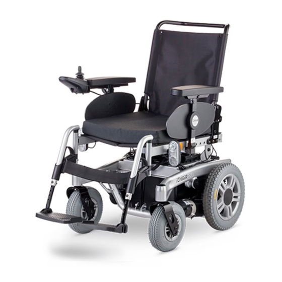
Page 10: Overview
OVERVIEW Model: 1.609 The overview shows the most important components and operating devices of the electric wheelchair. Pos. Description (1) Back support (2) Arm support (3) Operating module (4) Seat cushion (5) Leg support (6) Footplate (7) Front lighting (8) Selection lever drive-/push mode... -
Page 11: Handling The Electric Wheelchair
HANDLING THE ELECTRIC BRAKES WHEELCHAIR Service brake The motors work electrically as operating Securing the electric wheelchair brake and carefully brake the electric wheel- The electric wheelchair is to be secured as chair down without jerks to stillstand. follows to prevent it from rolling off unin- tentionally: Braking the wheelchair For allotted braking of the wheelchair slow-... -
Page 12: Locking The Brakes
Locking the brakes To engage the brakes swivel the selection lever drive-/push mode on both sides as far as possible into drive mode [1]. ☞ Activation of the selection lever is in- tended for an accompanying person. Attention: It should not be possible to push the electric wheelchair forward when the brakes are engaged. -
Page 13: Drive-/Push Mode
Drive-/push mode Attention: Only switch the electric wheelchair to push mode when it is standing still for positioning or in case of emergencies, but not on slopes/hills. ☞ The electric magnetic brakes are switched off in the push mode. – A braking of the electric wheelchair is then only possible by switching to the drive mode. -
Page 14: Selecting The Operation
SELECTING THE OPERATION In order to obtain operational readiness of the electric wheelchair the following direc- tions are to be carried out in the indicated order. ☞ Note: Charge the drive batteries via the oper- ating module before the first journey. 1. - Page 15 4. Switch the operating module on Press the ON/OFF-key (4) on the control panel of the operating module. ☞ Therefore observe operation manu- al < Operating module >.
-
Page 16: Pre-Operation Checks
Pre-operation checks Before starting to drive, the following should be checked: ☞ the battery charging condition, ☞ the setting of the preselected final speed. – – For this observe the operating manual < Operating module >. Battery charging procedure ☞ For the battery charging procedure also observe the operating manual of the battery charger. -
Page 17: Positioning The Operating Module
Positioning the operating module Function description You will find a detailed description of the keys and symbols in the operating manual for < Operating module >. The position of the operating module can be adjusted to suit the individual size of the user. -
Page 18: Leg Supports
LEG SUPPORTS Attention: Before any actions on the leg supports the wheelchair is to be secured against unintentional rolling motions. ☞ Therefore observe chapter Securing the electric wheelchair on page 11. Calf belt The removable calf belt (1) prevents the feet from sliding off the back of the footplates. -
Page 19: Lower Leg Support
Lower leg support The footplates are to be folded up for enter- ing or exiting the wheelchair [1]. ☞ Check the locking points! – Remove both feet from the footplates. – Remove the calf belt (2), if present. ☞ Therefore observe chapter Calf belt on page 18. -
Page 20: Leg Support Upper Part
Leg support upper part The upper leg support with an inserted lower leg support is termed leg support. Turning the leg supports to the side For easy transfer out of/into the electric wheelchair as well as driving closer to a closet, bed or bathtub the leg supports can be swivelled away toward the in-/outside [1] and [2]. -
Page 21: Swivelling In The Leg Supports
Swivelling in the leg supports For inward swivelling, let the leg supports swivel forward until the lock audibly engag- es [1]. ☞ Note: After audibly swivelling the leg sup- ports inward check the respective lock- ing device. ☞ Afterwards observe the chapter Lower leg support on page 19. -
Page 22: Removing The Leg Supports
Removing the leg supports For easy transfer into and out of the electric wheelchair as well as a reduced wheelchair length (important for transport) the leg sup- ports can be removed [1]. ☞ Note: Remove the calf belt before swivelling away the leg supports. -
Page 23: Arm Supports
ARM SUPPORTS Attention: Do not use the arm supports [1] to lift or carry the electric wheelchair. – Do not drive without the arm sup- ports! Removing the arm support To remove the arm support, loosen the clamping screw (2) first and then pull out the arm support toward the top . -
Page 24: Back Support
BACK SUPPORT The back support can be folded down for storage or transport. ☞ Note: For better demonstration of the wire cable (1) the back support is shown without cushion. Folding down the back support ☞ If required remove the seat pad (velcro fastener). -
Page 25: Secure Positions Of The Back Support
Any change to the seat inclination will on hills/slopes. lead to different safe back support ad- justments! Model 1.609 Seat inclina- safe position of the back support incli- Adjusted seat inclination tion nation [1] 2°... -
Page 26: Seat
SEAT Seat cushion The seat cushion is placed with the burling side onto the seat plate [1]. Seat inclination Attention: Only adjust the seat angle [2] when the electric wheelchair is standing on a horizontal, level surface. A danger of tipping over exists on gradients! The seat-angle adjustment is not linked with an automatic speed reduction... -
Page 27: Retaining Strap
RETAINING STRAP The retaining strap serves to strap in a per- son sitting in the electric wheelchair. – Additional stabilisation of the sitting position. – Prevents the user from sliding forwards out of the electric wheelchair. – Continuous adjustment to suit the us- er’s needs. -
Page 28: Lighting
< Electric in motor vehicles >! – This document and vehicles >! further information can be accessed on our website < www.meyra.com > in the < Download Archive >. LOADING AND TRANSPORTATION ☞ Do not use the back support, leg sup-... -
Page 29: Transport Security
Transport security The electric wheelchair is only to be secured through the securing points. ☞ The four anchor positions are marked with a symbol [1]. ☞ The procedure for securing the wheel- chair can be read in the document < Safety and general handling instruc- tions electric vehicles >... -
Page 30: Maintenance Schedule
Maintenance schedule WHEN WHAT REMARK Before starting out General Carry out test yourself or with a helper. Test for faultless operation. Checking the magnet- Carry out test yourself or with ic brake a helper. Move the selection lever If the electric wheelchair can for the drive/push mode be pushed, have the brakes into the drive mode posi-... - Page 31 WHEN WHAT REMARK Every 2 months Check tyre profile Carry out a visual check your- (depending dis- self or with a helper. Minimum tread = 1 mm tance covered) If the tyre profile is worn down or if the tyre is damaged, con- sult a specialist workshop for repairs.
-
Page 32: Fuses
Fuses Replacing the fuses Before replacing fuses, park the electric wheelchair on a level surface and secure it from rolling away. ☞ Therefore observe chapter Securing the electric wheelchair on page 11. Attention: Only replace the safety fuse with a safe- ty fuse of the same type! New fuses can be obtained for example at petrol stations. -
Page 33: Lighting
Lighting The lighting (1)+(2) is equipped with longlife LED-technology. ☞ Note: If a turn-signal bulb is defective, the re- maining one blinks at double frequen- ☞ Immediately have a defective LED-lamp repaired by a specialist workshop. Headlights The housing of the light (1) must be adjust- ed so that the light cone is visible on the driving surface. -
Page 34: Fault Correction
Fault correction Fault Cause Remedy Battery indicator on the Battery fuse is defective or Replace defective fuse or operating module does not correctly inserted. clean contacts and insert not light up after the correctly. switch-on. Plug connection of the Check the plug connec- power supply without... -
Page 35: Technical Data
TECHNICAL DATA – reduced driving speed (especially at walking speed). Kilometric performance In practical use, the kilometric performance under 'normal conditions' is then reduced Kilometric performance depends to a large to approx. 80 % – 40 % of the nominal value. extent on the following factors: –... -
Page 36: Model 1.609
Model 1.609 All data within the following table relates to the standard version of the stated model. Dimensional tolerance ± 1.5 cm, ± 2°. Model: ......................1.609 Type plate: ..................... at the front right on the battery bracket Class of use as per DIN EN 12184: ........................Class B Life span: .................................. -
Page 37: Battery Charger
Steering wheel: ø 225 x 70 mm (9“) pneumatic tyres: ................. (36 psi) max. 2.5 bar Drive wheel: ø 320 x 60 mm (12,5 x 2.5“) pneumatic tyres:..............(36 psi) max. 2.5 bar Axle: Horizontal position (with seat depth 46 cm) : ...................55 mm Transport dimensions: Length (incl. - Page 38 Performance - mechanical (view Kilometric performance): obstacle height upwards: ..........................max. 60 mm obstacle height downwards: ........................max. 60 mm Ground clearance (drive): ............................60 mm Ground clearance (battery tub): ........................80 mm Turning radius: ............................approx. 840 mm Turning area: ............................approx. 1300 mm max.
-
Page 39: Meaning Of The Labels On The Electric Wheelchair
Meaning of the labels on the electric wheelchair Attention! Read the operating manuals and other provided documen- tation. Do not lift the electric wheelchair at the arm supports or leg supports. Removable parts are not suitable for carrying. Drive mode Push mode Push only on level surfaces. -
Page 40: Meaning Of The Symbols On The Type Plate
Meaning of the symbols on the type plate Manufacturer Order number Serial number Production date (Year – Calendar week) Permitted user weight max. permissible total weight Permitted axle weights Max. permissible rising gradient Max. permissible falling gradient Permitted maximum speed The product is approved as a seat within a motor vehicle The product is not approved as a seat within a motor vehicle. -
Page 41: Inspection Certificate
INSPECTION CERTIFICATE Recommended safety inspection 1st year (at least every 12 months) Vehicle data: Stamp of specialist dealer: Model: Signature: Delivery note no.: Place, date: Serial-no.(SN): Next safety inspection in 12 months Date: Recommended safety inspection 2nd year Recommended safety inspection 3rd year (at least every 12 months) (at least every 12 months) Stamp of specialist dealer:... -
Page 42: Warranty / Guarantee
WARRANTY / GUARANTEE norm specifications cannot be declared as warranty or guarantee claims. We accept legal liability for this product Attention: within the scope of or general terms and Failure to observe the instructions in conditions and warranty and in certain cas- the operating manual, improperly car- es other verbal resp. -
Page 43: Warrantee / Guarantee Section
Warrantee / Guarantee section Please fill out! Copy if necessary and send the copy to the specialist dealer. Warranty / Guarantee Model designation: Delivery note no.: SN (view type plate): Date of delivery: Stamp of the specialist dealer: Inspection certificate for transfer Vehicle data: Serial-no.(SN): Stamp of specialist dealer:... - Page 44 Your specialist dealer MEYRA GmbH Meyra-Ring 2 D-32689 Kalletal-Kalldorf +49 5733 922 - 311 +49 5733 922 - 9311 info@meyra.de www.meyra.de MEYRA 1 075 397 (Status: 2014-07) All technical modifications reserved. Original operating manual.
Need help?
Do you have a question about the 1.609 and is the answer not in the manual?
Questions and answers
модель заднеприводная с альтернативным управлением или без ?