
Related Manuals for Stelpro STCNP


Summary of Contents for Stelpro STCNP
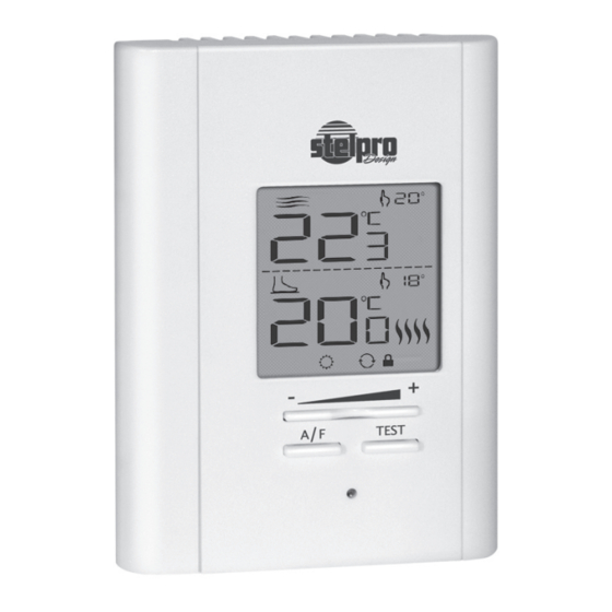
- Page 1 User’s Guide “STCNP” Heating floor non programmable electronic thermostat For further information or to consult this guide online, please visit our Web site. INSSTCNP5MA1010...
- Page 2 WARNING WARNING Before installing and operating this product, the owner and/or installer must read, under- stand and follow these instructions and keep them handy for future reference. If these in- structions are not followed, the warranty will be considered null and void and the manufac- turer deems no further responsibility for this product.
- Page 3 1. Description The STCNP non programmable electronic thermostat can be used to control heating floors with electrical current − with a resistive load − ranging from 0 A to 16 A at 120/208/240 VAC. It has an easy user interface. It keeps the temperature of a...
-
Page 4: Installation
Parts supplied: • one (1) thermostat; • two (2) mounting screws; • four (4) solderless connectors suitable for copper wires; • one (1) floor sensor. 2. Installation Thermostat selection and sensor location The thermostat must be mounted on a connection box, at around 1.5 m (5 feet) above the floor level, on a section of the wall exempt from pipes or air ducts. - Page 5 upward. 4. Align and secure the mounting base to the connection box using the two screws supplied. 5. Route wires coming from the wall through the hole of the mounting base and make the required connections using the “Four-wire installation” figure, and using the supplied solderless connectors.
- Page 6 to the other. Then, install the floor temperature sensor. Four-wire installation 6. Reinstall the front part of the thermostat on the mounting base and tighten the screw at the bottom of the unit. 7. Turn on the power. 8. Set the thermostat to the desired setting (see the following section).
-
Page 7: Operation
3. Operation (Ambient mode) (Floor mode) Automatic Day mode mode TEST Night mode GFCI button Red Indicator (GFCI Test) First Start-up At the first start-up, the thermostat is initially in the Day and modes. The temperature is displayed in degrees Celsius and the standard factory set point adjustment is 25°C. - Page 8 Temperature set points The figures beside the icon indicate the temperature set points (both in modes). They can be displayed in degrees Celsius or Fahrenheit (see “Display in degrees Cel- sius/Fahrenheit”). Out of any adjustment mode, press down the + button to in- crease the set point, or the - button to decrease it.
- Page 9 Night mode timer The Night mode features a timer that automatically returns to the Day mode after a selectable time period. This timer allows the temporary use of a temperature set point. The standard factory adjustment of the timer is 8 hours. With this adjustment, the thermostat automatically returns to Day mode 8 hours after being switched to the Night mode.
-
Page 10: Automatic Mode
to the latest recorded value when switching from the Day mode to the Night mode. It is not necessary to read- just the timer every time you switch to the Night mode. The timer is also reinitialized when this value is adjusted. Once the timer has completed its cycle and when the thermostat is in the Day mode, you must manually return to the Night mode. - Page 11 Adjustment procedure of the Automatic mode: 1. First, switch to the Night mode by simultaneously press- ing down the + and - buttons and releasing them imme- diately. 2. From the Night mode, simultaneously press down the + and - buttons for more than 3 seconds, until the icon starts to blink, indicating that the adjustment of the Night mode timer is effective.
- Page 12 (with a maximum set point temperature of 24°C) Sensor Selection If you want to use the STCNP thermostat of Stelpro Design with a temperature sensor already installed in the floor (other than the sensor supplied with this thermostat), you must con- tact the Stelpro Design customer service to validate the com- patibility between the sensor and the thermostat.
- Page 13 Temperature Control The thermostat controls the temperature (accord- ing to the mode) with a high degree of accuracy. When the heating starts or stops, it is normal to hear a “clic” sound. It is the noise of the relay which opens or closes, as applicable.
- Page 14 button to reinitialize the ground-fault circuit interrupter, the red indicator turns off. b) Failed test: The red indicator does not light up and the entire display blinks during 5 seconds. In this case, dis- connect the heating system at the electrical panel. Lock option This mode imposes a maximum temperature set point which is impossible to exceed regardless of the mode in progress.
- Page 15 Parameter backup and power failures The thermostat saves some parameters in its nonvolatile memory in order to recovere them when power is restored (e.g. after a power failure). These are the four set points (Day/ Night/ ), the Automatic mode, the Lock option, the maximum set point of the Lock option, the Celsius/Fahren- heit mode, the remaining time of the timer and the maximum floor temperature.
-
Page 16: Troubleshooting
4. Troubleshooting Problem Solution In normal operating conditions, the thermostat housing can reach The thermostat is hot. nearly 40°C at maximum load. It is normal and will not affect the operation of the thermostat. Check if the thermostat is properly Heating is always on. -
Page 17: Technical Specifications
5. Technical Specifications Supply voltage: 120/208/240 VAC, 50/60 Hz Maximum electrical current with a resistive load: 16 A 3840 W @ 240 VAC 3475 W @ 208 VAC 1920 W @ 120 VAC Range of temperature: 0 °C to 35 °C (0 °F to 95 °F) Temperature display resolution: 1 °C (1 °F) Range of the temperature set points:... -
Page 18: Limited Warranty
The warranty is limited to the factory repair or the replacement of the unit, and does not cover the cost of disconnection, transport, and installation. Customer service Stelpro Design Inc. 1041, Parent Street Saint-Bruno-de-Montarville (Quebec) Canada J3V 6L7 Email: contact@stelpro.com Web site: www.stelpro.com...
Need help?
Do you have a question about the STCNP and is the answer not in the manual?
Questions and answers