
Subscribe to Our Youtube Channel
Related Manuals for Stelpro STZB402 Plus


Summary of Contents for Stelpro STZB402 Plus
- Page 1 USER’S GUIDE STZB402+ ELECTRONIC THERMOSTAT FOR THE SMART HOME For further information or to consult this guide online, please visit our website at www.stelpro.com 042D07_INSSTZB402+0616...
- Page 2 WARNING Before installing and operating this product, the owner and/or installer must read, understand and follow these instructions and keep them handy for future reference. If these instructions are not followed, the warranty will be considered null and void and the manufacturer deems no further responsibility for this product.
-
Page 3: Installation
DESCRIPTION This thermostat is designed to control baseboard, convector and fan-forced heaters. It may be associated to a ZigBee network. This thermostat is NOT compatible with the following installations • Inductive load • Central heating system • Heating load outside the specified ratings (refer to the Technical Specifications section) Parts supplied •... - Page 4 Thermostat mounting and connection Cut off power supply on lead wires at the electrical panel in order to avoid any risk of electric shock. 2. If an existing thermostat is being replaced, remove the previous thermostat. 3. Ensure that the air vents of the Ki thermostat are clean and clear of any obstruction. 4.
-
Page 5: Wire Installation
6. Pass the wires from the wall through the hole at the base of the mounting base and connect them using the solderless connectors supplied. When making the connection with aluminum wire, make sure that you are using connectors identified CO/ALR. Please note that the thermostat wires do not have polarity. - Page 6 7. Place all the wires into the connection box. 8. Align the little slots located on the top of the thermostat with those on the mounting base and secure the thermostat to the mounting base. Note that you can also position the thermostat on the left or the right side of the junction box (see below).
-
Page 7: Operation
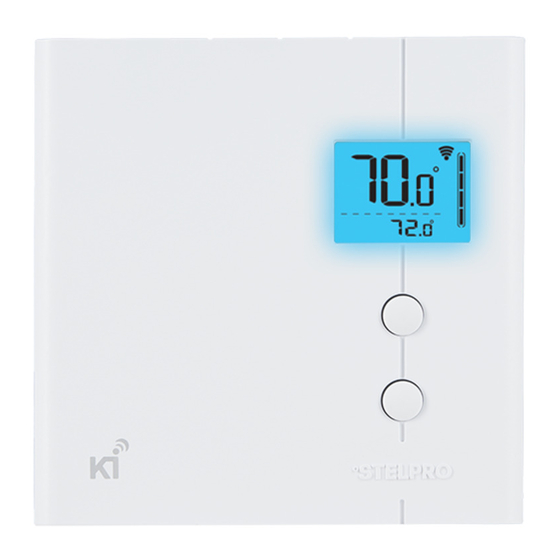
OPERATION Ambient temperature ZigBee connectivity Heating status Lock mode Fan mode Frost warning Advanced settings Thermostat mode Set point temperature OR outdoor temperature (requires external sensor over ZigBee) 042D07_INSSTZB402+0616... -
Page 8: Ambient Temperature
Ambient temperature The temperature is displayed either in °C with a 0.5 °C resolution or in °F with a 1 °F resolution. The screen will display LO if the temperature drops below 0 °C (32 °F) and will display HI if the temperature rises above 50 °C (122 °F). -
Page 9: Heating Mode
NOTE 1: Even in Off mode , the thermostat is still powered and electric shock is still possible. Always cut off the power supply when cleaning or removing the thermostat. NOTE 2: When in Off mode , the thermostat will not activate the heating element, therefore there is a risk of freezing. - Page 10 7. °STELPRO information menu: used to gain information on the product 7.1: Thermostat version 7.2: ZigBee radio version 7.3: Day of production 7.4: Month of production 7.5: Year of production 7.6: Baseboard/convector control checksum 7.7: Fan-forced heater control checksum ZigBee node Id...
-
Page 11: Factory Reset
To reset the thermostat to its default settings: - Enter the advanced settings - Enter the °STELPRO menu (menu 7) - Navigate to the (def) screen using the UP or DOWN buttons. - Enter the (def) menu by pressing the UP and DOWN buttons for less than 3 seconds - Select (yes) and confirm the selection by pressing the UP and DOWN buttons for less than 3 seconds. - Page 12 Refer to your ZigBee controller instructions manual to find how to associate both devices. On some ZigBee controllers, an app may be used to provide the outdoor temperature. TROUBLESHOOTING PROBLEM CODE DEFINITION Temperature is below 0 °C (32 °F), heating will be always active Temperature is above 50 °C (122 °F), heating will be always inactive Temperature sensor is defective, heating will always be inactive.
- Page 13 PROBLEM SOLUTION • In normal operating conditions, the thermostat housing The thermostat is hot may become hot at maximum load. That is normal and will not affect the effective operation of the thermostat. • Check if the thermostat is properly connected. Refer to Heating is always on the installation section.
-
Page 14: Supply Voltage
TECHNICAL SPECIFICATIONS Supply voltage 120/240 VAC, 50/60 Hz Minimum current with resistive load 1.25 A 300 W @ 240 VAC 150 W @ 120 VAC Maximum current with resistive load 16.7 A 4000 W @ 240 VAC 2000 W @ 120 VAC Temperature display range 0 °C to 50 °C (32 °F to 122 °F) Temperature display resolution... -
Page 15: Limited Warranty
The warranty is limited to the factory repair or the replacement of the unit, and does not cover the cost of disconnection, transport, and installation. E-mail: contact@stelpro.com Website: www.stelpro.com STELPRO | Saint-Bruno-de-Montarville | Quebec | J3V 6L7 042D07_INSSTZB402+0616...
Need help?
Do you have a question about the STZB402 Plus and is the answer not in the manual?
Questions and answers