Table of Contents
Advertisement
Quick Links
If you are viewing this guide online, please note
that this product has been slightly modified since
its introduction. To obtain the guide corresponding
to your model (fabrication date at the back of the
thermostat before January 2016), please contact
customer service.
For further information or to consult
this guide online, please visit our website
at www.stelpro.com
User's gUide
sTCP
multiple programming electronic
thermostat for heating floors
@
INSSTCP5MA0116
Advertisement
Table of Contents

Related Manuals for Stelpro STCPW5


Summary of Contents for Stelpro STCPW5
- Page 1 To obtain the guide corresponding to your model (fabrication date at the back of the thermostat before January 2016), please contact customer service. INSSTCP5MA0116 For further information or to consult this guide online, please visit our website at www.stelpro.com...
- Page 2 WArNiNg Before installing and operating this product, the owner and/or installer must read, understand and follow these instructions and keep them handy for future reference. If these instructions are not followed, the warranty will be considered null and void and the manufacturer deems no further responsibility for this product.
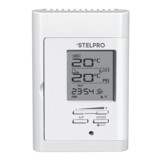
- Page 3 Description The STCP electronic thermostat can be used to control heating floors with electrical current − with a resistive load − ranging from 0 A to 16 A at 120/208/240 VAC. It has an easy user interface and can manage up to four programming periods a day.
-
Page 4: Installation
parts supplied: • one (1) thermostat; • two (2) mounting screws; • four (4) solderless connectors suitable for copper wires; • one (1) floor sensor. installation selection of thermostat and sensor location The thermostat must be mounted on a connection box, at around 1.5 m (5 feet) above the floor level, on a section of the wall exempt from pipes or air ducts. - Page 5 3. Using a screwdriver, loosen the screw retaining the mounting base and front part of the thermostat. Remove the front part of the thermostat from the mounting base by tilting it upard; 4. Align and secure the mounting base to the connection box using the two screws supplied;...
-
Page 6: Wire Installation
to the other. Then, connect the wires of the floor temperature sensor at the indicated location behind the thermostat. 4-wirE iNstallatioN 6. Reinstall the front part of the thermostat on the mounting base and tighten the screw at the bottom of the unit; 7. -
Page 7: Operation
operation Ambient temperature (Ambient mode) Floor temperature (Floor mode) Security mode first start-up At the first start-up, the thermostat is initially in the Man (manual) and modes. The temperature is displayed in degrees Celsius and the standard factory set point adjustment is 21°C. -
Page 8: Temperature Set Points
temperature set points The figures displayed beside the icon indicate the ambient ) or the floor ( ) temperature set points. They can be displayed in degrees Celsius or Fahrenheit (see “Display in degrees Celsius/Fahrenheit”). Out of any adjustment mode, press down the + button to increase the set point, or the - button to decrease it. - Page 9 At any time, you can exit the adjustment mode of the day and the hour by pressing down the Exit button or by not pressing any button during 1 minute. In case of a power failure, the thermostat is self-sufficient for 2 hours.
- Page 10 for the first time instead, the backlight will be activated. To quickly scroll through the set point values, press and hold down the button. From mode, the set points can range between 3 and 35°C and can only be adjusted by increments of 1°C (from 37 to 95°F;...
- Page 11 After programming a day of the week, you can copy this set- ting; see “Copy of the Programming”. 1. To access the Programming mode, press down the day of the week button that you want to program (Mon to Sun). Once you release the button, the selected day of the week is displayed, the icon blinks and the period number 1 blinks...
-
Page 12: Anticipated Start
2- Press down the button of another day to program it. 3- Press down the Exit button. Moreover, if you do not press down any button for more than 1 minute, the thermostat will exit the Programming mode. In all cases, the programming is saved. - Page 13 copy of the programming You can apply the programming of one day of the week to other days by copying the programming day by day or in block. To copy the programming day by day, you must: 1. Press down the source day button (day to be copied). 2.
- Page 14 3. Simultaneously press down the + and – buttons to erase the period programming. The hour displays --:-- and the set point displays -- to indicate that the programming is erased. 4. The erased period number blinks and you can select another period to be erased or exit the Programming mode following one of the 3 methods described above.
- Page 15 2. The Pre Prog icon and saved selected preprogramming are displayed. This preprogramming can range between 0 and 3. From the Pre Prog mode, you can choose the first 10 preprogrammings by pressing and releasing the Pre Prog button. Each time you press down the button, the preprogramming switches (from 0 to 9).
-
Page 16: Safe Mode
24°C.) sensor selection If you want to use the STCP thermostat of Stelpro with a temperature sensor already installed in the floor (other than the sensor supplied with this thermostat), you must contact the Stelpro customer service to validate the compatibility between the sensor and the thermostat. -
Page 17: Temperature Control
temperature control thermostat controls floor/ambient temperature (according to the mode) with a high degree of accuracy. When the heating starts or stops, it is normal to hear a “clic” sound. It is the noise of the relay which opens or closes, as applicable. -
Page 18: Security Mode
Failed test: The red indicator of the thermostat lights up and the display indicates E4. In this case, disconnect the heating system at the electrical panel and call Stelpro’s customer service. c) Failed test: The red indicator of the thermostat lights up and the display shows only the time. - Page 19 2. Restore the power supply to the thermostat. The icon will blink during a maximum of 5 minutes, indicating that you can deactivate the Security mode. 3. Simultaneously press down the + and - buttons for more than 10 seconds. The icon will then be hidden indicating that the Security mode is deactivated.
-
Page 20: Troubleshooting
trouBleshooting DeFeCTIVe PArT ProbleM or PArT To CHeCK • In normal operating conditions, the thermostat housing can reach nearly The thermostat is hot. 40°C at maximum load. It is normal and will not affect the operation of the thermostat. • Check if the thermostat is properly Heating is always on. -
Page 21: Technical Specifications
technical specifications supply voltage: 120/208/240 VAC, 50/60 Hz maximum electrical current with a resistive load: 16 A 3840 W @ 240 VAC 3330 W @ 208 VAC 1920 W @ 120 VAC temperature display range: 0 °C to 40 °C (32 °F to 99 °F) temperature display resolution: 1 °C (1 °F) temperature set point range (ambient mode):... -
Page 22: Limited Warranty
The warranty is limited to the factory repair or the replacement of the unit, and does not cover the cost of disconnection, transport, and installation. email : contact@stelpro.com Website : www.stelpro.com stElpro DEsigN iNC. | saint-Bruno-de-Montarville | Québec | J3V 6l7 INSSTCP5MA0116...
Need help?
Do you have a question about the STCPW5 and is the answer not in the manual?
Questions and answers
My thermostat is not working The programming and floor temps seems correct. When the thermostat is attached properly in wall it does not heat, but when the thermostat is our of wall attachment it works correctly?
@ed This would indicate the thermostat is probably shorting. All external wiring connections are good
After a 5 day power outage I reset our Stelpro thermostat. I am able to adjust the ambient termperature setting but the floor temperature setting is blank and will not respond to + or - inputs.
If the floor temperature setting on a Stelpro STCPW5 thermostat is blank and unresponsive after a power outage, check if the thermostat detects the floor sensor. If it fails to detect the sensor, it will automatically revert to a default mode with a set point of 21°C. If using a floor sensor not supplied with the thermostat, contact Stelpro customer service to verify compatibility using the sensor’s serial number and name.
This answer is automatically generated