Table of Contents
Advertisement
Quick Links
For more information on OPTEX products, contact your
dealer or visit our website listed below;
OPTEX CO., LTD.
5-8-12 Ogoto Otsu Shiga 520-0101 Japan
tel
: +81-77-579-8690
fax
: +81-77-579-7120
E-mail
: env@optex.co.jp
website : http://www.optex.co.jp/env/eng/
Distributed by
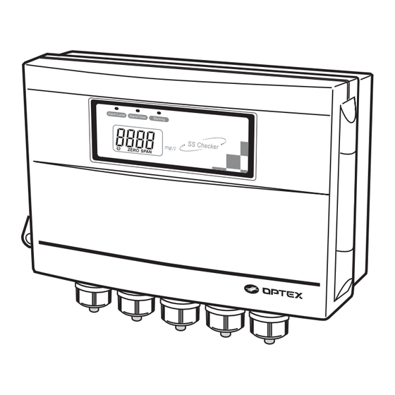
Transmitter
SC-T4
2007.7 59-1362-1
Instruction Manual
Thank you very much for purchasing OPTEX
Transmitter SC-T4.
All of this instruction manual must be read before
operation of the Transmitter SC-T4, for safe and proper
operation.
This instruction manual should be kept for future
reference such as maintenance.
Advertisement
Table of Contents

Related Manuals for Optex SC-T4


Summary of Contents for Optex SC-T4
- Page 1 Thank you very much for purchasing OPTEX Transmitter SC-T4. All of this instruction manual must be read before For more information on OPTEX products, contact your operation of the Transmitter SC-T4, for safe and proper dealer or visit our website listed below; operation. OPTEX CO., LTD.
-
Page 2: Table Of Contents
Thank you very much for purchasing OPTEX Transmitter SC-T4. All of this instruction manual must be read before operation of the Transmitter SC-T4, for safe and proper operation. 6.Fine Adjustment of Signal Output This instruction manual should be kept for future reference such as maintenance. -
Page 3: For Safe Use
Transmitter SC - T4 properly.] There high voltage parts inside Transmitter. Please thoroughly read the "For safe use" before using the SC-T4 Failure to observe properly. this precaution may cause fire or an Because these precautions are related to failure or malfunction, electric shock. -
Page 4: External Features
Cover Opening & Closing Procedure External Features Transmitter How to open the Cover Cover Lock Lever Key Hook Cable Clamps Operation panel Alarm Level Indicator (Green) 1. Slide up the Lock Lever. 2. Pull the Cover. Alarm Timer Indicator (Green) Warning Indicator (R ed ) Display Operation Buttons... -
Page 5: Installation
0.75 to 1.25 mm for the power cable. Use a circuit breaker with rated current of 2A or more for the power source of the SC-T4. Reference: When the Detector is in the air, analog ( 4-20mA ) signal output becomes... -
Page 6: Operation Panel
Extension of Detector Cable Operation Panel The standard Detector Cable is 10m. The Detector Cable shall be extended by referring to the Table below. Use a device such as a Pull-box if necessary. Move the digit to be entered using the right and left arrow buttons ( 0.1 digit 1000 digit ) . -
Page 7: Operation
Measurements Indication Calibration Be sure to carry out calibration according to the following procedure before using the SC-T4. Signal Output High Limit (20mA) Clean the Detector and the Detector Windows. Ex: The measurement value : 1000 mg/l Immerse the Detector in distilled water or ion-exchange water. -
Page 8: Alarm Relay Output Setting
Be sure to carry out calibration before setting these operations. When Err4, Err5, or Err6 is displayed, the SC-T4 is out of the setting range, or the Detector is not immersed in clean water during the 0-Adjustment, or the Detector Press and select the 0-Adjustment. - Page 9 Alarm Timer Setting Alarm Level Setting Alarm Timer can be set for 1 to 120 minutes or OFF. Alarm Level can be set for 1 to Span-Adjusted value or OFF. Setting unit is 1 minute. Setting unit is 1 mg/l. The Alarm Timer is set for OFF as a factory setting.
-
Page 10: Signal Output Response Time Setting
Signal Output Response Time Setting Signal Output Range Setting Signal Output Range can be set as follows. Signal Output Response Time can be set for 1 to 120 seconds or OFF. "High Limit" "Low Limit" Span-Adjustment value Setting unit is 1 second Ex) when the setting value of Span-Adjustment is changed to The Signal Output Response Time is set for OFF as a factory setting. -
Page 11: Fine Adjustment Of Signal Output
Fine Adjustment of Signal Output Press to terminate the Signal Output Range Low Limit Setting. Fine Adjustment of Lower Limit 4mA and Upper Limit 20mA of Signal CAUTION: Output (4-20mA) can be made. When Err6 is displayed, the value is out of the setting range. CAUTION: First make the Fine Adjustment of Lower Limit 4mA, and then make the Fine (2) Signal Output High Limit Setting... -
Page 12: Correction
Examine the correlation between values measured by the official connecting equipment such as recorder, make the Fine method and the values indicated by SC-T4 at a place where the Adjustments of the Upper Limit 20mA with the up and instrument is installed. -
Page 13: Error Indication
Error Indication Troubleshooting The SC-T4 has an Error Indication function to indicate improper Problem Cause Inspection and corrective action operation and occurrence of problem. There are six kinds of error The Detector is out of Check this according to the "Troubleshooting"... -
Page 14: Maintenance
Dimensions Calibration The SC-T4 is designed so as to make measurements stably for a long time. In order to maintain the reliability of measurement, however, carry out calibration at least once a year (Refer to page 10 ([5] Operation (1) Calibration)).
Need help?
Do you have a question about the SC-T4 and is the answer not in the manual?
Questions and answers