Table of Contents
Advertisement
Quick Links
INSTALLATION
& OPERATION
MANUAL
XP 9500 FLUSH-MOUNT LIGHTBAR
FLUSH-MOUNT LIGHTBAR
IMPORTANT:
Contents:
Introduction ............................................................. 2
Unpacking & Pre-Installation ................................... 2
Installation & Mounting ............................................ 3
Wiring Instructions ................................................... 4
LED Warning Devices ............................................. 4
Maintenance ............................................................ 6
Troubleshooting ....................................................... 7
Parts List ................................................................. 8
Dimensions ............................................................. 9
Notes ..................................................................... 10
Warranty ................................................................ 12
Read all instructions and warnings before installing and using.
INSTALLER:
This manual must be delivered to the end user of this equipment.
XP 9500
1
Advertisement
Table of Contents

Related Manuals for Code 3 XP9500


Summary of Contents for Code 3 XP9500
-
Page 1: Table Of Contents
INSTALLATION & OPERATION MANUAL XP 9500 FLUSH-MOUNT LIGHTBAR XP 9500 FLUSH-MOUNT LIGHTBAR Contents: Introduction ............. 2 Unpacking & Pre-Installation ........2 Installation & Mounting ..........3 Wiring Instructions ........... 4 LED Warning Devices ..........4 Maintenance ............6 Troubleshooting ............7 Parts List .............. -
Page 2: Introduction
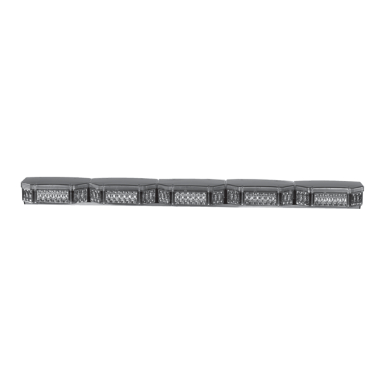
Introduction The XP9500 is an LED lightbar that contains a series of polycarbonate “pods” mounted to a strong aluminum extrusion. Angled lights in each pod project light to the intersections while forward facing lights provide a strong signal straight ahead. The PriZm LED lightheads provide a high intensity warning signal while drawing very little current. -
Page 3: Installation & Mounting
F R A M E A M B U L A N C E S H E E T M E T A L STANDARD CABLE HOLE LOCATIONS FOR XP9500 FROM CENTERLINE OF BAR 6 9/32" 1 POD 2 POD 3 POD 6 9/32"... -
Page 4: Wiring Instructions
1.5 x (number of 6/8/12-up modules being fused) + .5 x (number of 3-up modules being fused) Example: XP9500 lightbar with 7 forward facing 6-up modules and 16 angled and end facing 3-up modules Minimum fuse requirement for single fuse: (1.5 x 7) + (.5 x 16) = 18.5A minimum Note: Each 35 Watt halogen lamp requires 3A fusing. - Page 5 (example: Code 3® 925 or 700 series relay flasher). The flashing modules will have "Cycleflash" as the standard pattern. Flash patterns can be changed by shorting the 2-pin header, J1 as shown in Figure 3, momentarily then releasing.
-
Page 6: Maintenance
Remove the 2 sheet metal screws. Halogen assemblies are removed in the same manner. Before reassembling the top lens, make sure the gasket is properly seated. XP9500 TOP LENS T16320 - #8 SCREW REMOVAL PROCESS T16321 - #8 WASHER... -
Page 7: Troubleshooting
Troubleshooting All XP9500 lightbars are thoroughly tested prior to shipment. However, should you encounter a problem during installation or during the life of the product, follow the guide below for information on repair and troubleshooting. Additional information may be obtained from the factory technical help line at 314-996-2800. -
Page 9: Dimensions
XP 9500 OVERALL DIMENSIONS DESCRIPTION PODS LENGTH DEPTH HEIGHT XP9512 12.500 7.375 3.000 XP9525 25.062 7.375 3.000 XP9538 37.625 7.375 3.000 XP9550 50.188 7.375 3.000 XP9563 62.750 7.375 3.000 XP9575 75.313 7.375 3.000 XP9588 87.875 7.375 3.000... -
Page 10: Notes
NOTES:... - Page 11 NOTES:...
-
Page 12: Warranty
*Code 3 reserves the right to repair or replace product at its discretion. Code 3 assumes no responsibility or liability for expenses incurred for the removal and/or reinstallation of products requiring service and/or repair.
Need help?
Do you have a question about the XP9500 and is the answer not in the manual?
Questions and answers