Table of Contents
Advertisement
Quick Links
IMPORTANT! Read all instructions before installing and using. Installer: This manual must be delivered to the end user.
WARNING!
Failure to install or use this product according to manufacturer's recommendations may result in property damage, serious injury, and/
or death to those you are seeking to protect!
Do not install and/or operate this safety product unless you have read and understood the safety information
contained in this manual.
1.
Proper installation combined with operator training in the use, care, and maintenance of emergency warning devices are essential to
ensure the safety of emergency personnel and the public.
2.
Emergency warning devices often require high electrical voltages and/or currents. Exercise caution when working with live electrical
connections.
3.
This product must be properly grounded. Inadequate grounding and/or shorting of electrical connections can cause high current arcing,
which can cause personal injury and/or severe vehicle damage, including fire.
4.
Proper placement and installation is vital to the performance of this warning device. Install this product so that output performance of
the system is maximized and the controls are placed within convenient reach of the operator so that they can operate the system without
losing eye contact with the roadway.
5.
It is the responsibility of the vehicle operator to ensure daily that all features of this product work correctly. In use, the vehicle operator
should ensure the projection of the warning signal is not blocked by vehicle components (i.e., open trunks or compartment doors),
people, vehicles or other obstructions.
6.
The use of this or any other warning device does not ensure all drivers can or will observe or react to an emergency warning signal.
Never take the right-of-way for granted. It is the vehicle operator's responsibility to be sure they can proceed safely before entering an
intersection, drive against traffic, respond at a high rate of speed, or walk on or around traffic lanes.
7.
This equipment is intended for use by authorized personnel only. The user is responsible for understanding and obeying all laws
regarding emergency warning devices. Therefore, the user should check all applicable city, state, and federal laws and regulations. The
manufacturer assumes no liability for any loss resulting from the use of this warning device.
Specifications:
Size:
Full Unit
Pass Only Unit
Weight:
Full Unit
Pass Only Unit
Input Voltage:
Input Current:
Startup Current
Max Current:
(8) Light Hd (4) Multi/Single Ends & (4)
Single Color Tk Dn's or IF's Full Version
(6) Light Hd Multi or Single Color Full
Version
(4) Light Hd (2) Multi/Single Ends & (2)
Single Color Tk Dn's or IF's Pass Only
Version
(3) Light Hd Multi or Single Color Pass
Only Version
Installation and Operation Instructions
55.00"X1.25"X5.50"
*Including 18" Long Center Cable
18.75"X1.25"X5.50"
7.5 lbs
4.0 lbs
12VDC Nominal
0.007 Amps
11.30 Amps
9.20 Amps
5.70 Amps
4.60 Amps
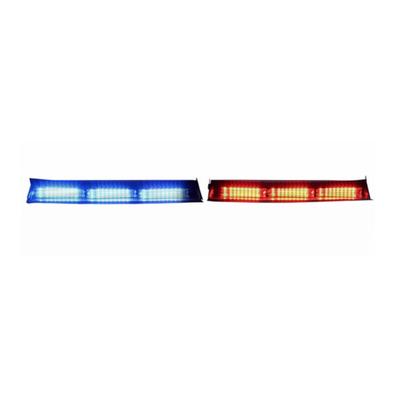
SuperVisor Flex™Series
Interior Lighting System
Unpacking and Pre-installation:
Carefully remove the Unit and place it on a flat surface, taking care
not to scratch the lenses or damage the cable coming out of the
Housing. Examine the unit for transit damage, broken optics, LED's,
etc. Report any damage to the carrier and keep the shipping carton.
Standard light bars are built to operate on 12 VDC negative ground
vehicles. If you have an electrical system other than 12 VDC nega-
tive ground, and have not ordered a specially wired light bar, contact
the factory for instructions.
Test the unit before installation. To test, touch the black wire to the
ground and the other wires to +12 VDC, in accordance with the
instructions attached to the cable (an automotive battery is prefer-
able for this test). A battery charger may be used, but note that some
electronic options may not operate normally when powered by a bat-
tery charger. If problems occur at this point, contact the factory!
Note: Before beginning the installation process, be absolutely
certain that the Light Bar functions as desired.
Page 1 of 12
Advertisement
Table of Contents

Subscribe to Our Youtube Channel
Related Manuals for Code 3 SuperVisor Flex Series


Summary of Contents for Code 3 SuperVisor Flex Series
- Page 1 Installation and Operation Instructions SuperVisor Flex™Series Interior Lighting System IMPORTANT! Read all instructions before installing and using. Installer: This manual must be delivered to the end user. WARNING! Failure to install or use this product according to manufacturer’s recommendations may result in property damage, serious injury, and/ or death to those you are seeking to protect! Do not install and/or operate this safety product unless you have read and understood the safety information contained in this manual.
-
Page 2: Wiring Instructions
Wiring Instructions: Route the Unit’s cable as desired and plug the Unit’s Driver Side Center Cable Connector into the Passenger Side Connector. Note: It is advisable to leave an extra loop of cable when installing the light bar to allow for future changes or reinstallations. Single Color Versions: For wiring the Single Color Versions of the SuperVisor Flex, connect the black lead to a solid frame ground, preferably the (-) or ground side of the battery, &... - Page 3 Wiring Instructions: Figure 1 Figure 2 Figure 3 Page 3 of 12...
- Page 4 Wiring Instructions: Figure 4 Figure 5 Figure 6 Page 4 of 12...
- Page 5 Wiring Instructions: Figure 7 Page 5 of 12...
- Page 6 Switching: Progressive vs. Independent Switching In a 3-level progressive switch application there are only 3 patterns that typically need to be set. Using the defaults in the Switching Table below, the patterns displayed would be as follows. Pattern 1: As the switch is moved from the off position (with the progressive levels notated in parentheses). The defaults listed in this manual are for the progressive 3 levels.
- Page 7 Flash Pattern Instructions: SUPERVISOR FLEX Multi Color Units INSTALLER NOTE: FLASH RATE + FLASH SEQUENCE = FLASH PATTERN Lighthead Flash Sequences - Multi Color Lighthead Flash Sequences - Multi Color Double Flash-75 - LEVEL - 2 DEFAULT LEFT / RIGHT PRIMARY &...
-
Page 8: Troubleshooting
Changing Flash Patterns: To change the flash patterns on the LED Light Heads, remove the mounting screws that attach the Cover to gain access to the printed circuit boards inside (see the exploded view on Page 10). Momentarily short and release the pattern change prongs as shown below to change patterns. - Page 9 Replacement Parts: SUPERVISOR FLEX Figure 8 Page 9 of 12...
- Page 10 Assembly Parts: SUPERVISOR FLEX Reference Number Part Description Quantity Outer Panel - Driver Side Sedan Version Outer Panel -Passenger Side Sedan Version Mounting Brkt-Slotted Light Blocker-Sedan Version 18LED Multi or 9 LED Single Color Light Head Module Up To 6 3 LED Torus Take Down Up To 4 Chassis-Driver Side...
- Page 11 Assembly Parts: SUPERVISOR FLEX Multi Color CC Box Figure 9 Reference Number Part Description Quantity E-Tray - Multi Color SuperVisor Power Ground Cable--Mass State Police Slick Top System PCB Central Controller-Midrange #6-32 X.375 Phil Rd M/S, Stl, Zinc Cover-CC Housing-Multi Color SuperVisor Label-CC Box-Multi Color SuperVisor Input Harness-Multi Color SuperVisor CC Box Output Harness-Multi Color SuperVisor CC Box...
-
Page 12: Product Returns
*Code 3®, Inc. reserves the right to repair or replace at its discretion. Code 3®, Inc. assumes no responsibility or liability for expenses incurred for the removal and /or reinstallation of products requiring service and/or repair.;...
Need help?
Do you have a question about the SuperVisor Flex Series and is the answer not in the manual?
Questions and answers