Table of Contents
Advertisement
INSTALLATION
& OPERATION
MANUAL
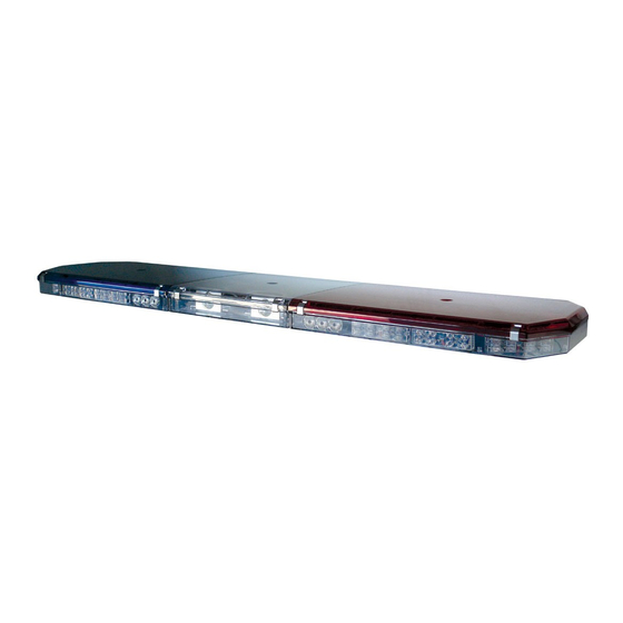
LED X™ 2100
LIGHTBAR
CONTENTS:
For future reference record your lightbar's serial no. here __________________________________________
IMPORTANT:
LED X
Introduction...................................................................................2
Unpacking & Pre-Installation.........................................................3
Installation & Mounting..........................................................3-5
Instructions..............................................................5-6
&
Specifications.................................................6-10
Maintenance.........................................................................10-11
Parts List (Replacement Parts / Exploded View).................12-13
Trouble Shooting.................................................................14-15
Warranty.....................................................................................16
Read all instructions and warnings before installing and using.
INSTALLER:
This manual must be delivered to the end user of this equipment.
1
™
2100
LIGHTBAR
Advertisement
Table of Contents

Related Manuals for Code 3 LED X 2100


Summary of Contents for Code 3 LED X 2100
-
Page 1: Table Of Contents
INSTALLATION & OPERATION MANUAL LED X™ 2100 LIGHTBAR ™ LED X 2100 LIGHTBAR CONTENTS: Introduction...................2 Unpacking & Pre-Installation............3 Installation & Mounting............3-5 Wiring Instructions..............5-6 Options & Specifications..........6-10 Maintenance.................10-11 Parts List (Replacement Parts / Exploded View)....12-13 Trouble Shooting..............14-15 Warranty..................16 For future reference record your lightbar's serial no. here __________________________________________ Read all instructions and warnings before installing and using. -
Page 2: Introduction
SAE standards. The LED X 2100 is designed on a modular basis, which means that the light bar can be customized to meet any requirement. The LED X 2100 has room for numerous halogen, incandescent and LED options. While we do not recommend a light installed in every location, the design of the LED X 2100 offers the ultimate flexibility in the location of warning and auxiliary lights. -
Page 3: Unpacking & Pre-Installation
Unpacking & Pre-installation Carefully remove the light bar and place it on a flat surface, taking care not to scratch the lenses or damage the cable coming out of the bottom. Examine the unit for transit damage, broken lamps, etc. Report any damage to the carrier and keep the shipping carton. Standard light bars are built to operate on 12 volt D.C. - Page 4 The special hooks are stainless steel and should be saved and reused. Mounting kit parts are available to permit remounting on vehicles of different design or make. Consult your local dealer or Code 3 , Inc. for detailed information. Permanent Mounting Typical Mounting: Refer to Figure 3.
-
Page 5: Wiring Instructions
The only significant difference between the LED X™ 2100 with optional ArrowStik ® and a conventional LED X 2100, is the additional, thinner cable exiting the bottom of the lightbar. The larger cable is the lightbar power cable. Route the wiring cable into the engine or passenger compartment, taking care to use grommets and to apply sealant around openings to keep water out. -
Page 6: Options & Specifications
- Refer to the control head manual packaged with the lightbar for control head installation and operation instruction. OPTIONS & SPECIFICATIONS Many options are available for the LED X 2100. This section is designed to describe the function of the various LED X 2100 options. LED WARNING MODULES This Product contains high intensity LED devices. - Page 7 Blue, Amber and White. The new OPTIX corner module is a ( 1" X 6" ) module and uses larger, higher efficiency, TIR optics to produce an enhanced corner signal over the exisitng ( 1" X 4" ) Code 3 LED X™ corner module. While the OPTIX will become the standard corner module for most configurations, the LED X corner module will still be available and may be required for some configurations.
- Page 8 6). The stationary versions can be flashed by connecting the module(s) to any flasher that does not require ground through the load (example: Code 3® 700 series relay flasher). The flashing modules will have "Cycleflash" as the standard pattern. The OPTIX and LEDX flash pattern can be changed by shorting the 2-pin header, J1 as shown in Figure 7, momentarily then releasing.
- Page 9 Directional module Flash Pattern - Table 2 Flash Pattern Description Cycle Flash Cycles through various patterns @ 70 fpm Steady-Burn Steady-Burn Five Flash Five Pulses per flash @ 70 fpm Quad Flash Four Pulses per flash @ 70 fpm Triple Flash Three Pulses per flash @ 70 fpm Double Flash Two Pulses per flash @ 70 fpm...
-
Page 10: Maintenance
Lens Cleaning Use plain water and a soft cloth, or Code 3® lens polish and a very soft paper towel or facial tissue. Because plastic scratches easily, cleaning is recommended only when necessary (about every six months). Do not subject the lenses to car washes that use brushes, as these will scratch the lenses. - Page 11 If attempting to clean the reflector, use only a mild glass cleaner and a very soft cloth. Do not attempt to use any wax type products as these will burn onto the reflector. Remove the reflector assembly by removing the appropriate fasteners, then remove the snap-on filter if necessary. In most cases, these lamps will be a bayonet style, so simply push in and turn counterclockwise to remove.
-
Page 13: Parts List (Replacement Parts / Exploded View)
Parts List (Reference numbers identify items shown in Figures on previous pages) Ref No. Description Part No. #8 x .250" Sheet Metal Screw T05029 #8 x .270" Sheet Metal Screw T01215 #8 x .375" Sheet Metal Screw T00243 5/16" Cable Clamp T00346 1/2"... -
Page 14: Troubleshooting
Troubleshooting All LED X™ 2100 Lightbars are thoroughly tested prior to shipment. However, should you encounter a problem during installation or during the life of the product, follow the guide below for information on repair and troubleshooting. Additional information may be obtained from the factory technical help line at 314-996-2800. - Page 15 Follow the guide below for information on repair and trouble shooting for the arrowstik option. ® ARROWSTIK OPTION TROUBLESHOOTING GUIDE SOLUTION POSSIBLE CAUSE PROBLEM QUESTIONS Arrowstik does not Are the front function when panel LED turned on. indicators operating properly? a.
-
Page 16: Warranty
*Code 3®, Inc. reserves the right to repair or replace at its discretion. Code 3®, Inc. assumes no responsibility or liability for expenses incurred for the removal and /or reinstallation of products requiring service and/or repair.; nor for the packaging, handling, and shipping: nor for the handling of products returned to sender after the service has been rendered.
Need help?
Do you have a question about the LED X 2100 and is the answer not in the manual?
Questions and answers