Table of Contents
Advertisement
Advertisement
Table of Contents

Related Manuals for Skymaster DCI 9410


Summary of Contents for Skymaster DCI 9410
- Page 1 Digital Satellite Receiver DCI 9410 Item no. 39722...
-
Page 2: Table Of Contents
Welcome to the new age of digital television! The DCI 9410 receives unencrypted digital TV programmes and, in addition, can also receive encrypted digital TV programmes from the various programme providers by the addition of two card readers (not included). -
Page 3: Safety Information
Mains voltage: Use the equipment with the voltage specified on the case only! Do not plug the equipment into the mains until all connection and installation work has been completed. Earthing: Antenna systems must always be earthed, paying heed to the pertinent local and VDE regulations. ASTRA, EUTELSAT, TÜRKSAT, DiSEqC and Skymaster are registered trademarks. -
Page 4: Information On Direct Satellite Reception
3. Information on direct satellite reception Selecting the antenna location. Viewed from Europe, all TV satellites are located in the south, therefore you must select the installation location so that the antenna points southwards. The satellite systems with the largest, freely receivable programme ranges are ASTRA (19.2°east) and HOTBIRD (13°east). - Page 5 3. Information on direct satellite reception The following EUROPE ASTRA 19,2° est HOTBIRD 13° est Brussels 30,1 31,2 setting angles Sarajewo 39,4 39,1 apply for the Copenhagen 26,3 26,6 various locations: Tallinn 22,4 21,9 Helsinki 21,6 21,0 Marseilles 38,1 39,5 Paris 31,6 33,0...
- Page 6 3. Information on direct satellite reception For precise alignment of the antenna, the complete cabling must now be connected. The television and the receiver should be located in the immediate vicinity of the antenna. It is almost impossible to align the reception system by “shouting” e.g. from a distant television. A SAT finder (art.
- Page 7 3. Information on direct satellite reception You must now move the preset antenna in millimetre steps, with the screws only hand-tight. Please note that there must not be any obstacles between antenna and reception direction, and that you must not stand in front of the antenna area.
-
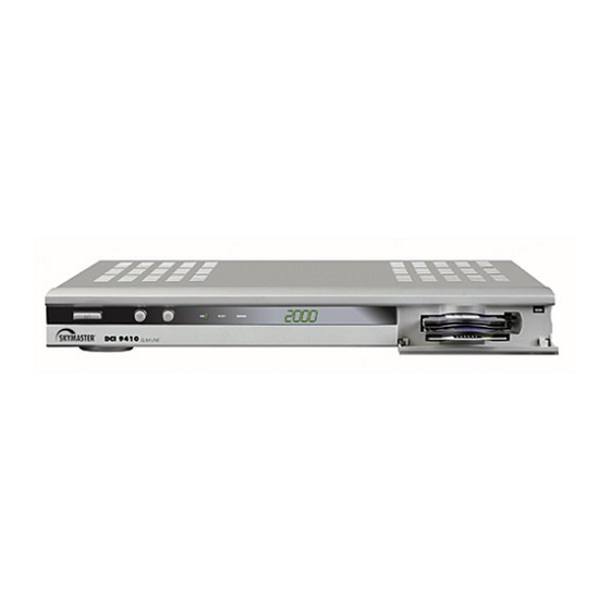
Page 8: Operator's Controls, Front Of Device
4. Operator’s controls, front of device CAM module not included 1. 7-segment display (programme indicator) 2. IR receiver for remote control 3. Satellite signal display 4. Stand By (Stand By display) 5. On (receiver switched on) 6. On/Off switch (Stand By mode) 7. -
Page 9: Remote Control
5. Remote control 4 in1 1. Sound On/Off Switches the sound off. Pressing again switches the sound back on 2. On/Off (Stand By) This button switches the satellite receiver on or to Stand By mode 3. TV (optional) No function 4. - Page 10 5. Remote control 4 in1 Your new remote control contains one of the largest infrared code library for 4 different devices obtainable in Europe. This remote control unit is preprogrammed, all you have to do is to choose the device which you wish to control (for example TV) and it’s 3-digit code number from the brand code list (for example 001 under Philips TV).
-
Page 11: Other Functions
5. Remote control 4 in1 C. Setting up by Manual Search: If setting up with brand name and codes is unsuccessful, you can also use the “Manual Search” to find the correct code for operating your device. 1. Switch on the device that you like to control. If it is a video recorder, insert a video cassette. 2. -
Page 12: Connections
6. Connections Connection to the SAT antenna The DiSEqC technology allows a large number of connection variants: • A permanently aligned SAT antenna • Two permanently aligned SAT antennae or a Multifeed antenna with DiSEqC 2-way switch (art. no. 3932) •... -
Page 13: Connecting To The Tv Unit, To A Video Recorder And To A Stereo System
6. Connections Connecting to the TV unit You use a SCART cable for connecting to the TV set. If you have a TV with a 16:9 screen, for example, you can adjust the settings to match your TV set in the receiver's screen menu. The default screen format is 4:3. If your TV set does not have a Scart socket, use an appropriate adapter or use the 3 cinch outputs (Video/Audio L/R), or S-VHS connector (S-VHS/Audio L/R). -
Page 14: Performance Features
• Go To X - Automatic calculation of SAT positions • Volume control via remote control • SAT signal output for analogue SAT receivers • Short circuit proof • RS232 interface • On/Off switch Subject to technical changes ASTRA, EUTELSAT, TÜRKSAT, DiSEqC and Skymaster are registered trademarks. -
Page 15: Quick Start - Commissioning
You will find a complete description of all menus during the further course of these operating instructions. The following descriptions will help you with setting your SKYMASTER digital receiver and your satellite antenna. There are two possible delivery status for the device: The device is already pre-programmed (ASTRA programmes) and is ready for immediate operation, or the “Welcome”... -
Page 16: The Osd Menu: The Most Important Functions
As with your TV unit, you only need a few functions for daily use: Programme change, volume control and a few special functions, such as e.g. Teletext. You will hardly need the remote control for your TV set in future, as you can control all previous and additional functions via the SKYMASTER remote control! Programme change: 0 - 9 For direct entry of the programme location (e.g. -
Page 17: The Osd: Info Window, Sound Channels And Volume
9.1 The OSD: Info window, sound channels and volume Programme information: After switching on or changing over, an info window appears, which pro- vides you with various information about the programme: Date/Time Programme name Broadcast title Broadcast from/to (time) Teletext available/not available Subtitles (“S”... -
Page 18: The Osd: Programme Selection, Programme Lists
9.2 The OSD: Programme selection, programme lists With the constantly increasing range of programmes, confusion naturally increases too: Many programmes are only of regional significance (e.g. foreign language), many programmes are encoded and can only be received with a special receiver, for a fee, or are just plain uninteresting. To ensure clarity and order in the programme lists, there are 4 favourites lists and various sorting criteria. -
Page 19: The Osd: Special Functions, Teletext And Epg
9.3 The OSD: Special functions, Teletext and EPG Hold picture: You can hold the picture by pressing the FREEZE button, similar to the pause function on a video recorder. The sound will remain audible. Press the button again to display the normal TV picture. Display subtitles: On occasion subtitles are transmitted for the current broadcast, e.g. -
Page 20: Call Up And Close Osd Menu
9.4 Call up and close OSD menu If you press the MENU button, the main menu will appear on the screen. Further submenus can be opened via the main menu, and settings changed on your receiver. You can change the appearance of the OSD, add or delete programmes, adjust the receiver to your SAT system, load new software via satellite and much more. -
Page 21: Osd Setup Menu
9.6 OSD SETUP menu The Setup menu contains all extended setting options. Some menus can only be called up by entering a password (default setting 0000). You can change this password under CHILD-PROOF. Please make a note of the new password and keep it in a safe place! To open the SETUP menu, press the MENU button and select SETUP with the control keys. -
Page 22: Delete Satellite
9.6 OSD SETUP menu Delete satellite To open the “Delete satellite” menu, press the MENU button and select SETUP and “Satellite/TP” with the control keys. Then press OK. You will obtain an overview of all set satellites. Select the satellite to be deleted and confirm the deletion with OK. -
Page 23: Transponder Settings
9.6 OSD SETUP menu Transponder settings The “Transponder settings” submenu firstly provides you with an overview of all stored transponders. The following actions can be performed by pressing the 4 coloured buttons: RED: A new search for the selected transponder GREEN: Changes picture and sound parameters (for experts only!) YELLOW: Deletes the selected transponder... -
Page 24: Managing Favourites
9.7 Managing favourites Often the programme list contains several hundred programmes, many of which you will never or only seldom watch. However, you will switch on certain programmes again and again. You can transfer these programmes into four different favourite programme lists, which can be quickly accessed by pressing the four coloured buttons on the remote control. -
Page 25: Programme Management
9.8 Programme management Press the MENU button and then select SETUP and PROGRAMMES. You can edit the programme list of all stored programmes in the PROGRAMME MANAGEMENT submenu: RED: Definitive deletion of one or several programmes GREEN: Moves a programme to another position YELLOW: Access to the programme only after entering the password BLUE: Rename/change programme name... -
Page 26: Lnb Settings
10. LNB settings Up to 8 LNBs (reception converters) can be connected to your satellite receiver. You can change the default settings for each LNB in the LNB SETTINGS menu and, for example, set how further LNBs are to be actuated via a DiSEqC switch. -
Page 27: Diseqc 1.2 - Rotor Control
11. DiSEqC 1.2 - Rotor control An outstanding feature of the DCI 9410 is the control of a rotating antenna system via the antenna cable. To activate the control, switch the function ON in the DiSEqC 1.2 menu. The following conditions are necessary: A correctly aligned rotating system with a DiSEqC 1.2 rotor. -
Page 28: Settings
13. Settings In the SETUP submenu SETTINGS, you can set the receiver time, the timer for automatic switching on and off for up to 6 programmes, change the password and adjust the receiver settings to the connected television set. Time settings You have 2 options for making time settings: “Automatic”... -
Page 29: Child-Proofing
13. Settings Child-proofing You can lock individual programmes with content unsuitable for younger viewers (see PROGRAMME MANAGEMENT menu) and certain menus against unauthorised access by using a password. You can switch the password protection on or off in the TV SETTINGS menu (SETUP ->... -
Page 30: Extended Settings
“Software update” option. If the latest software cannot be loaded via the satellite, you can find it at our web site www.skymaster.de. The software can be loaded via the RS232 interface on the back of the device. -
Page 31: Information
14. Information The INFORMATION menu contains two submenus: Signal strength and Information (device and software version). Signal strength The information window not only shows the signal strength of the programme (and transponder) that is switched on, but also the frequency, polarisation and the symbol rate. -
Page 32: Trouble-Shouting Guide
15. Trouble-shooting guide Note the position of the mains switch and switch the unit on if necessary No Function (4.1 Operator’s controls, back of device, Page 54, Item 12). (no signal indication on the device and via the signal indications in the OSD): No antenna signal 1. -
Page 33: Sat Lexicon
16. SAT lexicon – Explanations of technical terms 22 kHz pulse: This pulse, generated by the receiver, is used to control switches or to switch • •• ••al LNBs to the digital range. Analogue programmes: In comparison with digital signals, analogue signals require a considerably greater quantity of information. With the constantly increasing range of programmes, the bandwidths available would no longer suffice in the long term. - Page 34 16. SAT lexicon – Explanations of technical terms Transfer switch: Transfer switches (sometimes integrated into multi-switches) are required to fan-in SAT and terrestrial signals. These must be separated again by “reversed” transfer switches or SAT connection boxes. Reception frequency: As with VHF reception, each satellite programme has a reception frequency. In contrast to tuning a radio transmitter, further settings are necessary (polarisation, DiSEqC/22kHz/LO frequency)! If e.g.
- Page 35 16. SAT lexicon – Explanations of technical terms Multi-switches: Multi-switches are used in SAT distribution systems (from 3 subscribers/receivers). Multi-switches have at least 2 LNB connections for 1 double LNB (horizontal 18 V and vertical 13 V, possibly terr. input). In digitally compatible or Multifeed systems, at least 4 LNB inputs are required: horizontal 18 V, vertical 13 V, horizontal 18 V + 22 kHz and vertical 13 V + 22 kHz.
- Page 36 16. SAT lexicon – Explanations of technical terms SCART: 21-pin plug standard for bidirectional image and sound transmission. Switching voltages and data can also be transmitted. 10-pin scart cables are sufficient for a satellite receiver or VHS video recorder. If a decoder or Super-VHS video recorder is used, 21-pin scart cables must be used! There are 3 common standards, which must be set on the video recorder or television so that the picture signal of the SAT receiver can be transmitted faultlessly: FBAS (setting on TV/video e.g.
-
Page 37: Service, Hot-Line, Adress
(D) 09• 0•• •512 532 (€ 0,2• /Min.) Monday to Su• day from 8.00 - 22.00 SM ELECTRONIC GmbH Waldweg 2 D-22145 Stapelfeld/• •••• Internet: www.skymaster.de E-Mail: info@sm-electronic.de Subject to technical changes ASTRA, EUTELSAT, TÜRKSAT, DiSEqC and Skymaster are registered trademarks. - Page 38 99039722-03/2005...
Need help?
Do you have a question about the DCI 9410 and is the answer not in the manual?
Questions and answers