
Subscribe to Our Youtube Channel
Related Manuals for National Semiconductor LM26LV


Summary of Contents for National Semiconductor LM26LV
- Page 1 Revision A July 16,2007 LM26LV Evaluation Board User’s Guide © Copyright 2007 National Semiconductor Corporation www.national.com...
-
Page 2: Table Of Contents
1.0 Introduction 1.1 Block Diagram 2.0 Quick Start 2.1 Quick Start Diagram 3.0 Functional Description 3.1 LM26LV Evaluation Board Connection Table 4.0 Electrical and Mechanical Specifications 4.1 Electrical Specifications 4.2 Electrical Schematic 4.3 Evaluation Board Layout 4.4 Bill of Materials 4.5 Mechanical Specifications... -
Page 3: Lm26Lv Evaluation Board User's Guide
References 1. “LM26LV 1.6V, LLP-6, Factory Preset Temperature Switch and Temperature Sensor” datasheet. The latest copy of the LM26LV datasheet can be obtained by going to the National Semiconductor websitewww.national.com, by searching on “LM26LV”, and then downloading the LM26LV.pdf file. -
Page 4: Introduction
TRIP TEST mode. The LM26LV Evaluation Board offers the user a convenient way to experiment with Note that R1 is only in the circuit for the operation of the LM26LV Temperature protection. -
Page 5: Quick Start
2.0 Quick Start jumpered for normal operation. Jumpering J2 will put the LM26LV in TRIP TEST mode, not for normal operation. The diagram below shows how the LM26LV is connected in a typical bench Apply power to the LM26LV evaluation test configuration. -
Page 6: Functional Description
Jumper is installed across pins 1 and 2 by default. Output Otherwise resistor R3 is in series with the output. Use these pins to test and monitor the signals on Test Pins the board. Do not inject signals here. © Copyright 2007 National Semiconductor Corporation www.national.com... -
Page 7: Electrical And Mechanical Specifications
+1.6 VDC to The Board uses the +1.6 VDC to +5.5 VDC and GND lines from an external low-noise power supply. +5.5 VDC 4.2 Electrical Schematic Figure 4.2 Schematic Diagram of the LM26LV Evaluation Board © Copyright 2007 National Semiconductor Corporation www.national.com... -
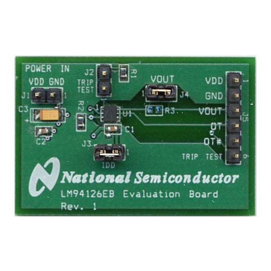
Page 8: Evaluation Board Layout
4.3 Evaluation Board Layout Figure 4.3 Layout diagram of the LM26LV Evaluation Board © Copyright 2007 National Semiconductor Corporation www.national.com... -
Page 9: Bill Of Materials
25°C 70°C 4.5.2 Evaluation Board Basic Dimensions 1.650 in/ 4.191 cm 4.5.3 Electrostatic Discharge (ESD) Precautions The user shall use ESD precautions as specified in National Semiconductor ESD document (SC)CSI-3-038 available through www.national.com. © Copyright 2007 National Semiconductor Corporation www.national.com... - Page 10 BANNED SUBSTANCE COMPLIANCE National Semiconductor certifies that the products and packing materials meet the provisions of the Customer Products Stewardship Specification (CSP-9-111C2) and the Banned Substances and Materials of Interest Specification (CSP-9- 111S2) and contain no ‘‘Banned Substances’’...
Need help?
Do you have a question about the LM26LV and is the answer not in the manual?
Questions and answers