Garland GI-MO/DU 7000 Installation And Operation Manual
Induction module-line cooktops dual/quad
Hide thumbs
Also See for GI-MO/DU 7000:
- Service manual (20 pages) ,
- Installation, operation and maintenance manual (64 pages)
Table of Contents
Advertisement
Quick Links
INSTALLATION AND
OPERATION MANUAL
GARLAND INDUCTION
MODULE-LINE COOKTOPS
DUAL/QUAD
with RTCSmp TECHNOLOGY
Real-time Temperature Control System
multi-point sensing
CE models comply with the latest European
Norms:
EN 60335-1, EN 60335-2-36, EN 62233 (EMC/EMV)
North American models: ETL listed in
compliance with UL 197, CSA C22.2 No.109, NSF-4
Complies with FCC part 18, ICES-001
FOR YOUR SAFETY
DO NOT STORE OR USE GASOLINE OR OTHER
FLAMMABLE VAPORS OR LIQUIDS IN THE VICINITY
OF THIS OR ANY OTHER APPLIANCE
Users are cautioned that maintenance and repairs must be performed by a Garland authorized service agent using only genuine
Garland replacement parts. Garland will have no obligation with respect to any product that has been improperly installed,
adjusted, operated or not maintained in accordance with national and local codes and/or installation instructions provided with
the product or any product that has its serial number defaced, obliterated or removed, and/or which has been modified or
repaired using unauthorized parts or by unauthorized service agents. For a list of authorized service agents and/or genuine
replacement parts, please visit our website at
visit
www.manitowocfoodservice.com.
superseded and is subject to change without notice.
Part # 4532415 Rev 1 (12/12/13)
www.garland-group.com for USA and Canada.
The information contained herein, including design and part specifications, may be
Visit our Video Gallery at
www.Garland-Group.com
Models:
GI-MO/DU 7000
GI-MO/DU 7000 (FL)
GI-MO/DU 10000
GI-MO/DU 14000 (FL)
PLEASE READ ALL SECTIONS OF THIS MANUAL AND
RETAIN FOR FUTURE REFERENCE.
THIS PRODUCT HAS BEEN CERTIFIED AS COMMERCIAL
COOKING EQUIPMENT AND MUST BE INSTALLED BY
PROFESSIONAL PERSONNEL AS SPECIFIED
INSTALLATION
AND ELECTRICAL CONNECTION MUST
COMPLY WITH CURRENT CODES:
IN CANADA – THE CANADIAN ELECTRICAL CODE PART 1
AND / OR LOCAL CODES.
IN USA – THE NATIONAL ELECTRICAL CODE ANSI / NFPA
– CURRENT EDITION.
WARNING
IMPROPER INSTALLATION, ADJUSTMENT, ALTERATION,
SERVICE OR MAINTENANCE CAN CAUSE PROPERTY
DAMAGE, INJURY, OR DEATH. READ THE INSTALLATION,
OPERATING AND MAINTENANCE INSTRUCTIONS
THOROUGHLY BEFORE INSTALLING OR SERVICING THIS
EQUIPMENT
© 2013 Garland Commercial Ranges Limited
GI-MO/QU 14000
GI-MO/QU 20000
GI-MO/QU 21000
GI-MO/QU 24000
GI-MO/QU 28000 (FL)
For international customers, please
Advertisement
Table of Contents

Related Manuals for Garland GI-MO/DU 7000


Summary of Contents for Garland GI-MO/DU 7000
- Page 1 THOROUGHLY BEFORE INSTALLING OR SERVICING THIS EQUIPMENT Users are cautioned that maintenance and repairs must be performed by a Garland authorized service agent using only genuine Garland replacement parts. Garland will have no obligation with respect to any product that has been improperly installed,...
-
Page 2: Using This Manual
RTCSmp Built-In Module-Line Dual/Quad Cooktops WARRANTY Our warranty statements for induction products are available on-line. Please visit our website at www.garland-group.com/minisite/service to download the latest revision. If you might have any questions, please contact Garland. USING THIS MANUAL This manual contains important information regarding safety, installation, operation, maintenance, and troubleshooting. -
Page 3: Table Of Contents
Installation and Operation Manual RTCSmp Built-In Module-Line Dual/Quad Cooktops CONTENTS Safety Requirements ......................5 1.1 Risk Involved By Disregarding Safety Information ....................5 1.2 Safety Instructions for Operator ............................. 5 1.3 Improper Use of the Equipment ............................. 6 1.4 Unauthorized Modification and Use of Spare Parts ....................6 1.5 Pan Detection .................................. - Page 4 Installation and Operation Manual RTCSmp Built-In Module-Line Dual/Quad Cooktops 6.2 Proper Placement of Cookware ............................ 33 6.3 Power Control ..................................34 6.4 No Pan No Heat ................................... 35 6.5 When Unit is Not In Use ..............................35 Cleaning ..........................36 Maintenance ..........................
-
Page 5: Safety Requirements
Risk Involved By Disregarding Safety Information Disregarding the safety instructions may cause harm to people, the surroundings, and the induction unit. Garland is not responsible for any damages or personal injury caused by failure to observe the safety requirements. -
Page 6: Improper Use Of The Equipment
Unauthorized Modification and Use of Spare Parts Please contact Garland if you intend to make any changes on the induction unit. For safety reasons, always use genuine parts and accessories approved by Garland. Any unauthorized modification as well as any installation of unapproved components will void all warranty. -
Page 7: Pan Detection
Safety Requirements RTCSmp Built-In Module-Line Dual/Quad Cooktops Pan Detection Energy is transferred to cookware if and only if the induction system detects a suitable pan on the heating area. The green indicator light signals to communicate the Pan Detection process: •... -
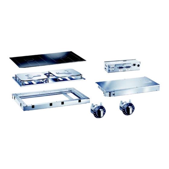
Page 8: Application, Components Overview
Application, Components Overview RTCSmp Built-In Module-Line Dual/Quad Cooktops Application, Components Overview Application The unique RTCSmp Module-Line Cooktops are specially engineered for building the most flexible kitchen operation. The Module-Line Family offers a wide selection of cooking surfaces: single, dual, quad cooktops with round, full or a combination of round and full induction coils. - Page 9 Application, Components Overview RTCSmp Built-In Module-Line Dual/Quad Cooktops Coil Carrier Sheet: Multiple options available: round or full coil in single, dual, quad, or combination of round/full coil configurations. | Compact and low profile design. Full Coil (FL): Rectangular in shape. Several large or small pans can be placed on one surface at the same time.
-
Page 10: Dimensions And Technical Specifications
Glass Size Models Product Function (mm) GI = MO = DU = Dual 7000, 10000 360 x 360, GI-MO/DU 7000/10000 -360 Garland module-line 650 x 375, GI-MO/DU 7000/10000 -650 induction 720 x 360 GI-MO/DU 7000/10000 -720 DU = Dual 7000, 14000... -
Page 11: Electrical Specifications
Voltage Power # Coils Circuits Size Zones 208 V AC/ 3Ph/ 60Hz 7000W(2x3500 W)/ 22A AWG 10 GI-MO/DU 7000-360FL 400 V AC/ 3Ph/ 50Hz 7000W(2x3500 W)/ 11A 1.5mm rectangular coils 440 V AC/ 3Ph/ 50Hz 7000W(2x3500 W)/ 10A 1.5mm 208 V AC/ 3Ph/ 60Hz... -
Page 12: Operating Conditions
Dimensions and Technical Specifications RTCSmp Built-In Module-Line Dual/Quad Cooktops Operating Conditions Max. Tolerance of Nominal Supply Voltage +6 /-10 % Network Impedance (Zmax.) 0.25Ω Supply frequency 50/60 Hz Amperage Nominal Value — 400V, 3Ph 10A for the 7kW generator (4 x 1.5mm 15A for the 10kW generator (4 x 2.5mm 2 x 10A for the 14kW generator (2 x (4 x 1.5mm Amperage Nominal Value —... -
Page 13: Installation
Installation RTCSmp Built-In Module-Line Dual/Quad Cooktops Installation IMPORTANT • Kitchen designers and installation contractors are responsible for designing and installing correctly the appropriate support structures and ventilation system for the cooking equipment. • When designing kitchen cabinets for the induction equipment, please take into account all installation requirements, including factors such as: ease of electrical installation, size of the power conductor, and length of the wires. -
Page 14: Induction Generator
Installation RTCSmp Built-In Module-Line Dual/Quad Cooktops The call-outs in the illustrations show: (C) Hot air exhaust from the generator. (D) Air intake through the air intake opening on the generator. (E) Louvered air exhaust opening installed on the cabinet. (F) Control Unit mounted to the underside of the countertop. (G) Mounting frame. -
Page 15: Dimensions
Installation RTCSmp Built-In Module-Line Dual/Quad Cooktops • It is highly recommended that an exhaust fan be installed into the cabinet at an appropriate location. This will force hot air out the cabinet and away from the induction unit. Consult an electrical or installation expert for the most appropriate location to install a cabinet exhaust fan. -
Page 16: Control Unit And Operation Unit/Power Switches
Installation RTCSmp Built-In Module-Line Dual/Quad Cooktops Control Unit and Operation Unit/Power Switches 4.3.1 Location • Distance of the control unit from the coil carrier sheet: MAX. 31.50” / 80cm. • Distance of the control unit from the operation unit (power switch): MAX. 31.50” / 80cm. •... -
Page 17: Dimensions Guide (Holes/Studs)
Installation RTCSmp Built-In Module-Line Dual/Quad Cooktops 4.3.5 Dimensions Guide (Holes/Studs) Dimensions in mm [inch] Coil Carrier Sheet, Ceran Glass and Mounting Frame The module-line cooktops are to be flush mounted. The cooktop assembly composes of a Ceran glass top, coil carrier sheet(s), and mounting frame. -
Page 18: Dimensions - Mounting Frame [For Glasstop Size 360X360Mm]
Installation RTCSmp Built-In Module-Line Dual/Quad Cooktops • Ensure the installed location of the generator is safe from any ingress of liquid into the immediate vicinity. • The coil carrier sheet can be installed around heat-producing equipment such as an oven, if and only if the ambient temperature is below 104°F (40°C). -
Page 19: Dimensions - Mounting Frame [For Glasstop Size 375X650Mm]
Installation RTCSmp Built-In Module-Line Dual/Quad Cooktops 4.4.3 Dimensions – Mounting Frame [for glasstop size 375x650mm] 4.4.4 Dimensions – Mounting Frame [for glasstop size 650x650mm] Part # 4532415 Rev 1 (12/12/13) Page 19... -
Page 20: Dimensions - Mounting Frame [For Glasstop Size 360X720Mm]
Installation RTCSmp Built-In Module-Line Dual/Quad Cooktops 4.4.5 Dimensions – Mounting Frame [for glasstop size 360x720mm] 4.4.6 Dimensions – Mounting Frame [for glasstop size 720x720mm] Part # 4532415 Rev 1 (12/12/13) -
Page 21: Installation Steps
Installation RTCSmp Built-In Module-Line Dual/Quad Cooktops 4.4.7 Installation Steps IMPORTANT • COUNTERTOP CUT-OUT DIMENSIONS are specified in the mounting frame drawings. • The mounting frames are to be stud-mounted onto the underside of the countertop. The minimum thickness of the countertop for mounting the frame is 1.5 mm / 0.06 inches, which is about 16-gauge. The maximum thickness for this application is 3.00 mm / 0.12 inches, which is about 10-gauge. - Page 22 Installation RTCSmp Built-In Module-Line Dual/Quad Cooktops D. Examine the Ceran glass before installation. Then carefully lower the glass onto the silicone stripe. NOTE: When installing multiple glass-tops on the same counter, ensure to orient all the logos on the glass-tops the same direction. Align the edges of the glass with the edges of the countertop cut-out.
- Page 23 Installation RTCSmp Built-In Module-Line Dual/Quad Cooktops While holding the coil carrier sheet with the retaining rails, swing the rails back into the original position and tighten the screws. The coils and temperature sensors installed on the coil carrier sheet must exert a constant pressure of 5mm to the Ceran glass.
-
Page 24: Models, Components And Cable Connections
Installation RTCSmp Built-In Module-Line Dual/Quad Cooktops Models, Components and Cable Connections 4.5.1 CHART 1 – Module-Line Round Coil Dual Models Part # 4532415 Rev 1 (12/12/13) -
Page 25: Chart 2 - Module-Line Round Coil Quad Models
Installation RTCSmp Built-In Module-Line Dual/Quad Cooktops 4.5.2 CHART 2 – Module-Line Round Coil Quad Models Part # 4532415 Rev 1 (12/12/13) Page 25... -
Page 26: Chart 3 - Module-Line Full Coil Dual Models
Installation RTCSmp Built-In Module-Line Dual/Quad Cooktops 4.5.3 CHART 3 – Module-Line Full Coil Dual Models Part # 4532415 Rev 1 (12/12/13) -
Page 27: Chart 4 - Module-Line Full Coil Quad Models
Installation RTCSmp Built-In Module-Line Dual/Quad Cooktops 4.5.4 CHART 4 – Module-Line Full Coil Quad Models Part # 4532415 Rev 1 (12/12/13) Page 27... -
Page 28: Chart 5 - Module-Line Full And Round Coil Quad Models
Installation RTCSmp Built-In Module-Line Dual/Quad Cooktops 4.5.5 CHART 5 – Module-Line Full and Round Coil Quad Models Part # 4532415 Rev 1 (12/12/13) -
Page 29: Electrical Installation
Installation RTCSmp Built-In Module-Line Dual/Quad Cooktops Electrical Installation All electrical connections must be installed by a qualified electrician. IMPORTANT • Refer to the electrical specifications in chapter 3 Dimensions and Technical Specifications AND the rating plate/instruction labels on the unit. Always refer to the rating plate/instruction labels on the unit to verify the electrical data. - Page 30 Installation RTCSmp Built-In Module-Line Dual/Quad Cooktops Connecting the components: IMPORTANT: • Always connect the cables according to the labels affixed next to the connectors and on the cables. • The cables—coils, sensors, CAN/BUS, mains— must be connected correctly. • Ensure the insertion tongues of the RJ-45 cable (CAN/BUS) are fully engaged. •...
-
Page 31: Function Test
Function Test RTCSmp Built-In Module-Line Dual/Quad Cooktops Function Test IMPORTANT When the unit is in use, the cookware will warm up the glass-top. To CAUTION avoid burn injuries, do not touch the glass-top. • Remove all objects from the glass-top and verify that the glass-top is not cracked or broken. Do not continue if the glass-top is cracked or broken. -
Page 32: Operating Instructions
Operating Instructions RTCSmp Built-In Module-Line Dual/Quad Cooktops Operating Instructions IMPORTANT • Induction units are more powerful, heat up pans quicker, and cook food faster than conventional cooking equipment. Your induction unit will require different use and care than other conventional equipment. Do not operate the induction equipment without reading this manual and follow all safety requirements. -
Page 33: Proper Placement Of Cookware
Operating Instructions RTCSmp Built-In Module-Line Dual/Quad Cooktops Boil Test To verify the performance of a pan for induction cooking: Add one liter of cold water into the pan and bring it to boil. The time needed to boil one liter of water should be: Coil with 3500W, approximately 140 seconds ... -
Page 34: Power Control
Operating Instructions RTCSmp Built-In Module-Line Dual/Quad Cooktops CORRECT. One pan for each ROUND coil. Each pan is placed in the center of the cook-zone. CORRECT. One large pan is placed in the center of a cook-zone for RECTANGULAR coils. CORRECT. Multiple pans are placed within one cook-zone for RECTANGULAR coils. -
Page 35: No Pan No Heat
Operating Instructions RTCSmp Built-In Module-Line Dual/Quad Cooktops No Pan No Heat Energy is transferred to cookware when the induction system detects a suitable pan on the heating area. The green indicator light signals to communicate the Pan Detection process: • When the unit is ON without any pan on the glass-top, the green indicator light flashes;... -
Page 36: Cleaning
/Cleaning RTCSmp Built-In Module-Line Dual/Quad Cooktops Cleaning The cleaning of the Ceran glass is identical to cleaning other similar glass surfaces. You may use any regular glass cleaning products available from a hardware store. Ensure NO LIQUID CAN ENTER into the induction unit. -
Page 37: Maintenance
Important Rules RTCSmp Built-In Module-Line Dual/Quad Cooktops Maintenance Maintenance and servicing work other than cleaning as described in this manual must be done by an CAUTION authorized service personnel. Do not open the induction unit – dangerous electric voltage inside! The induction unit may only be opened by an authorized service personnel. -
Page 38: 10 Troubleshooting
Only an authorized service technician would have the training and correct tools to diagnose the internal components accurately and thoroughly. Contact a Factory Authorized Service agency for assistance. For a list of Garland authorized service agencies, please visit our website www.garland-group.com. Part # 4532415 Rev 1 (12/12/13) -
Page 39: 10.2 Problems And Possible Causes
Troubleshooting RTCSmp Built-In Module-Line Dual/Quad Cooktops 10.2 Problems and Possible Causes Problem Possible Causes Action To Take By Operator Pan does not heat, green No power supply. Check the electrical supply, e.g. power cable LED lamp is OFF (dark) plugged into the wall socket. Check primary fuses. -
Page 40: Troubleshooting With Error Codes (For Service Technicians)
4 short flashes. And it repeats until the error is cancelled. To obtain the internal data and error code for troubleshooting, you need an IR Adapter, proper connectors, and software. The table below is a reference guide. For further information and assistance, please contact Garland Technical Service. - Page 41 Troubleshooting RTCSmp Built-In Module-Line Dual/Quad Cooktops NOTES: Part # 4532415 Rev 1 (12/12/13) Page 41...
- Page 42 Troubleshooting RTCSmp Built-In Module-Line Dual/Quad Cooktops NOTES: Part # 4532415 Rev 1 (12/12/13)
- Page 43 Installation and Operation Manual RTCSmp Built-In Module-Line Dual/Quad Cooktops CORRECT DISPOSAL OF THIS PRODUCT This marking shown on the product indicates that the product should not be disposed as household waste or regular commercial waste. Instead it shall be handed over to the applicable collection point for the recycling of electrical and electronic equipment.
- Page 44 Installation & Operation Manual GARLAND INDUCTION MODULE-LINE DUAL/QUAD COOKTOPS with RTCSmp TECHNOLOGIES Garland Commercial Ranges Ltd. T. 1-905-624-0260 USA Sales, Parts and Service 1-800-424-2411 1177 Kamato Road, Mississauga, F. 1-905-624-5669 Canadian Sales 1-888-442-7526 Ontario, CANADA L4W 1X4 www.garland-group.com Canada or USA Parts/Service 1-800-427-6668...
Need help?
Do you have a question about the GI-MO/DU 7000 and is the answer not in the manual?
Questions and answers