Exmark Laser Z XS Operator's Manual
Diesel models
Hide thumbs
Also See for Laser Z XS:
- Operator's manual (52 pages) ,
- Operator's manual (44 pages) ,
- Operator's manual (56 pages)
Table of Contents
Advertisement
Advertisement
Table of Contents

Related Manuals for Exmark Laser Z XS


Summary of Contents for Exmark Laser Z XS
-
Page 1: Diesel Models
For Serial Nos. 720,000 & Higher LAZER Z ® DIESEL MODELS Place Model No. and Serial No. Date Purchased Label Here (Included in the Literature Pack) or Fill in Below Engine Model No. and Spec. No. Model No. Engine Serial No. (E/No) Serial No. - Page 2 Replacements may be ordered through the engine manufacturer. Exmark reserves the right to make changes or add improvements to its products at any time without incurring any obligation to make such changes to products manufactured previously.
- Page 3 (6) line items or less. 4. If order is received by 3:00 p.m. central time, Exmark ships part(s) direct to dealer or customer, as requested by distributor, same day, overnight UPS, Exmark bills the distributor for parts and shipping charges, where applicable.
-
Page 4: Introduction
All Exmark parts are thoroughly tested and inspected before leaving the factory, however, attention is required on your part if you are to obtain the fullest measure of satisfaction and performance. -
Page 5: Table Of Contents
Contents Adjustments ............. 38 Deck Leveling ..........38 Pump Drive Belt Tension....... 38 Introduction ............4 Mule Drive Belt Tension Adjustment ..... 38 Safety ..............6 Deck Belt Tension ........39 Safety Alert Symbol ......... 6 Alternator Belt Tension ......... 39 Safe Operating Practices ........ -
Page 6: Safety
• Evaluate the terrain to determine what accessories ALERT! YOUR SAFETY IS INVOLVED! and attachments are needed to properly and safely perform the job. Only use accessories and attachments approved by Exmark. • Wear appropriate clothing including safety glasses, Figure 2 substantial footwear, long trousers, and hearing 1. - Page 7 Safety DANGER WARNING In certain conditions diesel fuel is extremely Diesel fuel is harmful or fatal if swallowed. flammable and vapors are explosive. Long-term exposure to vapors has caused cancer in laboratory animals. Failure to use A fire or explosion from diesel fuel can burn caution may cause serious injury or illness.
-
Page 8: Slope Operation
Safety • Be sure all drives are in neutral and parking brake • Stop the blades, slow down, and use caution when is engaged before starting engine. Use seat belts. crossing surfaces other than grass and when transporting the mower to and from the area to •... -
Page 9: Maintenance And Storage
Safety Using the Rollover Protection System (ROPS) A Rollover Protection System (roll bar) is installed on the unit. WARNING There is no rollover protection when the roll bar is down. Wheels dropping over edges, ditches, steep banks, or water can cause rollovers, which may result in serious injury, death or drowning. - Page 10 Safety • Carefully release pressure from components with WARNING stored energy. Hydraulic fluid escaping under pressure • Disconnect battery or remove spark plug wire can penetrate skin and cause injury. Fluid before making any repairs. Disconnect the accidentally injected into the skin must be negative terminal first and the positive last.
-
Page 11: Safety And Instructional Decals
Exmark equipment dealer or labels. distributor or from Exmark Mfg. Co. Inc. • Replace all worn, damaged, or missing safety • Safety signs may be affixed by peeling off the signs. - Page 12 Safety 98-5954 103-1798 103–0223 103-6936 103–0261 103-7218...
- Page 13 Safety 109-0872 109-1214 107-2102 109-1215 107-2112...
- Page 14 Safety 109-2263 109-1399 109-2264 109-2478 109-1921 109-2219...
- Page 15 Safety 109-6855 109–7949 19426-87881 109-2951 19426-87903 109-3148...
- Page 16 Safety 107-9866 1. Fast 2. Slow 3. Neutral 4. Reverse...
-
Page 17: Specifications
Note: Motion control levers are adjustable to • Fuel Filter: In-line 15 Micron two heights. Exmark P/N 98-7612. – Separate levers, on each side of the console, • Fuel Shut-Off Valve: 1/4 turn increments control speed and direction of travel of the (“OFF”, right tank, left tank, ) -
Page 18: Dimensions
Specifications • Armrests: Molded adjustable flip-up armrests. – 72 inch Deck: 24.75 inches (62.9 cm) • Seat Safety Switch: Incorporated into the • Blade Spindles: Solid steel spindles with 1.18 inch Safety Interlock System. Time delay seat switch (30 mm) I.D. bearings. eliminates rough ground cut-outs. -
Page 19: Torque Requirements
Specifications Overall Length: Bolt Location Torque Anti-Scalp Roller Nyloc 30-35 ft-lb (41-47 N-m) 60 inch 66 inch 72 inch Nut See Figure 10 Deck Deck Deck Anti-Scalp Roller Hex 50-55 ft-lb (68-75 N-m) Roll Bar - 81.9 inches 83.4 inches 85.8 inches Capscrew See Figure 10 (208.0 cm) -
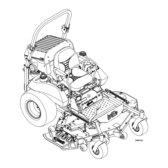
Page 20: Product Overview
Operation Product Overview Operation Note: Determine the left and right sides of the machine from the normal operating position. Controls Motion Control Levers The motion control levers located on each side of the console control the forward and reverse motion of the machine. -
Page 21: Hour Meter
Operation and “START”. Insert key into switch and rotate Drive wheel release valves are used to release the clockwise to the “ON” position. Rotate clockwise to hydrostatic drive system to allow the machine to be the next position to engage the starter (key must be pushed without the engine running. -
Page 22: Pre-Start
Operation Operating Instructions The voltmeter measure the voltage output of the alternator. Both high and low voltages will potentially damage the battery. Raise the Rollover Protection System (ROPS) Glow Plug Switch and Light Important: Lower the roll bar only when Located on the right fuel tank. -
Page 23: Stopping The Engine
Operation Engaging the PTO 2. Pull up and back on the parking brake lever to engage the parking brake. DANGER 3. Push in on the PTO switch to the “STOP” position. The rotating blades under the mower deck Note: It is not necessary for the operator to be are dangerous. -
Page 24: Driving The Machine
Operation 6. Allow the engine to run for a minimum of 15 seconds, then turn the ignition switch to the “OFF” position to stop the engine. 7. Remove the key to prevent children or other unauthorized persons from starting engine. 8. -
Page 25: Adjusting The Cutting Height
Operation deck lift assist lever located at the front right corner of the floor pan. Note: When changing the cutting height positions, always come to a complete stop and disengage the PTO. Figure 8 1. Lever in transport and 5 inch (12.7 cm) cutting height position Figure 7 1. -
Page 26: Transporting
Operation 6. Place the rollers in one of the positions shown (Figure 9). Rollers will maintain 3/4 inch (19 mm) clearance to the ground to minimize gouging and roller wear or damage. Figure 9 For cutting heights above 4.0 inches (102 mm) use the Figure 10 bottom hole. - Page 27 Operation Important: Do Not attempt to turn the unit WARNING while on the ramp, you may lose control and drive off the side. Loading a unit on a trailer or truck increases the possibility of backward tip-over. Avoid sudden acceleration when driving up a ramp Backward tip-over could cause serious injury and sudden deceleration when backing down a ramp.
-
Page 28: Maintenance
Maintenance Maintenance Note: Determine the left and right sides of the machine from the normal operating position. WARNING WARNING While maintenance or adjustments are being The engine can become very hot. Touching made, someone could start the engine. a hot engine can cause severe burns. Accidental starting of the engine could Allow the engine to cool completely before seriously injure you or other bystanders. -
Page 29: Periodic Maintenance
Maintenance Maintenance Service Maintenance Procedure Interval • Replace the air cleaner elements. (May need more often under severe conditions. See the Every 600 hours Engine Owner’s Manual for additional information.) • Change engine coolant. Dex-Cool© extended life coolant (orange color) Every 4,000 hours Monthly •... -
Page 30: Check Mower Blades
(grass) side of blade. thrown out from under the deck resulting in serious personal injury or death. Always install the original Exmark blades, blade bushings, and blade bolts as shown. Check Safety Interlock System... -
Page 31: Check Rollover Protections Systems (Roll Bar) Pins
See the Engine Owner’s Manual for additional Note: If machine does not pass any of these tests, information.) do not operate. Contact your authorized EXMARK SERVICE DEALER. 1. Stop engine, wait for all moving parts to stop, and remove key. Engage parking brake. -
Page 32: Change Engine Oil
Maintenance Check Hydraulic Oil Level 5. Check the condition of the inner element. Replace whenever it appears dirty, typically every other Service Interval: Every 40 hours time the paper element is replaced. Clean the base around the inner element before removing, so 1. -
Page 33: Lubricate Grease Fittings
Maintenance 3. Remove left and right belt shields on deck and lift up floor pan to inspect deck drive belt. 4. Check under machine to inspect the mule drive belt. Refer to Mule Drive Belt Tension Adjustment section in Adjustments. Lubricate Grease Fittings Note: See chart for service intervals. -
Page 34: Lubricate Brake Handle Pivot
Service Interval: Every 160 hours 7. Insert one bearing, one new seal into the wheel. 1. Stop engine, wait for all moving parts to stop, and Note: Seals (Exmark P/N 103-0063) must be remove key. Engage parking brake. replaced. 2. Unhook seat latch and tilt seat up. -
Page 35: Change Hydraulic System Filter
Yearly thereafter remove nut and install washer (P/N 1-523157) between hub and nut. Note: Use only Exmark P/N 103-2146. 4. Torque the slotted nut to 125 ft-lb (169 N-m). 1. Stop engine, wait for all moving parts to stop, and remove key. -
Page 36: Change Engine Coolant
Maintenance WARNING CAUTION Engine coolant is hot and pressurized and Engine coolant is toxic. Swallowing coolant radiator and surrounding parts are hot. Spray can cause poisoning. or steam from hot, pressurized liquid in the • Do Not swallow. engine cooling system and touching a hot •... -
Page 37: Thread Locking Adhesives
Maintenance • Sheave retaining bolt in the end of engine WARNING crankshaft. Engine compartment contains open belt • Caster wheel spacer nuts. drives, fans, and other rotating components • Fuel tank bulkhead fitting nuts. that can cause injury. Fingers, hands, loose clothing, or jewelry can get caught by the •... -
Page 38: Adjustments
Maintenance Adjustments front swivel using locking nut in front of swivel. Repeat for right side. Note: Disengage PTO, shut off engine, wait for 11. Recheck that the 3/4 inch (19 mm) blocks fit just all moving parts to stop, engage parking brake, and snugly under the brackets and that the tension on remove key before servicing, cleaning, or making any all the chains is approximately equal. -
Page 39: Deck Belt Tension
Maintenance side engine deck support, is positioned between the centers of the two alignment holes in the left support plate (Figure 16 and Figure 17). It is necessary to adjust the belt tension when the center of the bolt head is at or below the center of the bottom alignment hole. -
Page 40: Brake Link Adjustment
Maintenance be 1/8 inch (3.2 mm) away from the belt, with bolt-end of guide near end of slot (Figure 18). 4. If adjustment is necessary, loosen the bolt securing the belt guide and make proper adjustment. Tighten hardware. Figure 18 Figure 19 1. -
Page 41: Electric Clutch Adjustment
Maintenance Electric Clutch Adjustment Motion Control Linkage Adjustment No adjustment necessary. WARNING Reverse Indicator Adjustment Engine must be running and drive wheels must be turning so motion control 1. Stop engine, wait for all moving parts to stop, and adjustment can be performed. Contact with remove key. -
Page 42: Motion Control Damper Adjustment
Maintenance wheel must stop turning or slightly creep in reverse (Figure 22). Figure 21 Figure 22 Right-Hand Side of Unit Left-Hand Side of Unit 1. Turn here to adjust 2. Loosen here (right-hand 1. Turn LH tracking adjustment knob. (Do Not loosen any thread) nuts on LH side) 6. -
Page 43: Caster Pivot Bearings Pre-Load Adjustment
Maintenance Caster Pivot Bearings Cleaning Pre-Load Adjustment Clean Engine Cooling Remove dust cap from caster and tighten nyloc System nut until washers are flat and back off 1/4 of a turn to properly set the pre-load on the bearings. Service Interval: Before each use or daily If disassembled, make sure the spring washers are (May be required more reinstalled as shown in Figure 24. -
Page 44: Clean Grass Build-Up Under Deck
Maintenance Battery Disposal Important: Do Not use water to clean engine. Use low pressure compressed air. See Engine Owner’s Manual. DANGER Battery electrolyte contains sulfuric acid, Clean Grass Build-Up Under which is poisonous and can cause severe Deck burns. Swallowing electrolyte can be fatal or if it touches skin can cause severe burns. -
Page 45: Troubleshooting
Troubleshooting Troubleshooting Important: It is essential that all operator safety mechanisms be connected and in proper operating condition prior to mower use. When a problem occurs, do not overlook the simple causes. For example: starting problems could be caused by an empty fuel tank. The following table lists some of the common causes of trouble. - Page 46 Troubleshooting Problem Possible Cause Corrective Action Engine overheats. 1. Engine load is excessive. 1. Reduce the ground speed. 2. Oil level in the crankcase is low. 2. Add oil to the crankcase. 3. Dirty air filter. 3. Clean or replace the air cleaner element. 4.
- Page 47 Troubleshooting Problem Possible Cause Corrective Action Warning buzzer emits intermittent beep. 1. Oil level is low. 1. Check oil level. 2. Oil leaking from engine. 2. Contact Authorized Service Dealer.
-
Page 48: Schematics
Schematics Schematics Electrical Diagram G006167... - Page 49 Schematics Hydraulic Diagram...
- Page 50 No Claim of breach of warranty shall be cause for cancellation included with the product. or rescission of the contract of sale of any Exmark mower. All warranty work must be performed by an authorized Some states do not allow exclusions of incidental or...
- Page 52 Steerable Sulky Sulky Hitch Kit Turf Striper Standon Check Us Out On The Web: www.exmark.com © 2004–2007 Exmark Mfg. Co., Inc. Part No. 4500-169 Rev. A Industrial Park Box 808 (402) 223-6300 Beatrice, NE 68310 Fax (402) 223–5489 All Rights Reserved...
Need help?
Do you have a question about the Laser Z XS and is the answer not in the manual?
Questions and answers