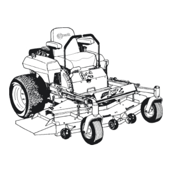
Exmark Laser Z Operator's Manual
Laser z series
Hide thumbs
Also See for Laser Z:
- Operator's manual (64 pages) ,
- Specifications (2 pages) ,
- Operator's & parts manual (40 pages)
Table of Contents
Advertisement
Advertisement
Table of Contents
Troubleshooting

Related Manuals for Exmark Laser Z


Summary of Contents for Exmark Laser Z
- Page 2 Public Resource Code. To acquire a spark arrester for your unit, see your Engine Service Dealer. Exmark reserves the right to make changes or add improvements to its products at any time without incurring any obligation to make such changes to products manufactured previously. Exmark, or its distributors and dealers, accept no responsibility for variations which may be evident in the actual specifications of its products and the statements and descriptions contained in this publication.
- Page 3 UPS, Exmark bills the distributor for parts and shipping charges, where applicable. The customer pays for the part and freight if it is shipped under the Exmark Parts Plus and if it arrives in accordance to the program.
- Page 4 If additional information is needed, or should you require trained mechanic service, contact your authorized Exmark equipment dealer or distributor. All Exmark equipment dealers and distributors are kept informed of the latest methods of servicing and are equipped to provide prompt and efficient service in the field or at their service stations.
-
Page 5: Table Of Contents
TABLE OF CONTENTS 1. SAFETY PAGE Safety Alert Symbol ................1 Training....................1 Preparation ..................1-3 Operation ................... 4-5 Maintenance & Storage..............5-7 Safety Signs..................7-10 2. SPECIFICATIONS Model Numbers................... 11 Engine ....................11 Fuel System..................11 Electrical System ................11-12 Cooling System................... -
Page 6: Safety Alert Symbol
RESULT IN PERSONAL INJURY IF PROPER PRECAUTIONS ARE NOT TAKEN. 1.2 TRAINING 1.2.1 Regard the Exmark mower as a piece of power equipment and teach this regard to all who operate this unit. 1.2.2 Read the instructions carefully. Familiarize yourself with the controls and the proper use of the equipment. - Page 7 WARNING POTENTIAL HAZARD Engine exhaust contains carbon monoxide, which is an odorless deadly poison. WHAT CAN HAPPEN Carbon monoxide can kill you and is also known to the State of California to cause birth defects. HOW TO AVOID THE HAZARD Do not run engine indoors or in a small confined area where dangerous carbon monoxide fumes can collect.
- Page 8 DANGER POTENTIAL HAZARD In certain conditions gasoline is extremely flammable and highly explosive. WHAT CAN HAPPEN A static charge can ignite gasoline vapors. A fire or explosion from gasoline can burn you, others, and cause property damage. HOW TO AVOID THE HAZARD Purchase and store gasoline only in an approved container.
-
Page 9: Operation
1.4 OPERATION Although hazard control and accident prevention are partially dependent upon the design and configuration of the equipment, these factors are also dependent upon the awareness, concern, prudence and proper training of the personnel involved in the operation, transport, maintenance and storage of the equipment. It is essential that all Operator Safety Mechanisms be connected and in operating condition prior to use for mowing. -
Page 10: Maintenance & Storage
1.4.5 Use EXTREME caution when backing up. LOOK BEHIND YOU! 1.4.6 Stop the blades when crossing surfaces other than grass and when transporting the mower to and from the area to be mowed. 1.4.7 Never operate the mower with damaged guards, shields, or covers. Always have safety shields, guards, switches, and other devices in place and in proper working condition. - Page 11 1.5.4 Store fuel in a container specifically designed for this purpose in a cool, dry place. 1.5.5 Keep the mower and fuel container in locked storage to prevent children from playing or tampering with them. 1.5.6 Gasoline powered equipment or fuel containers should not be stored in a basement or any enclosed area where open pilot lights or heat appliances are present.
-
Page 12: Safety Signs
When new components are installed, be sure that current safety signs are affixed to the replaced components. 1.6.4 New safety signs may be obtained from your authorized Exmark equipment dealer or distributor or from Exmark Mfg. Co. Inc. 1.6.5 Safety signs may be affixed by peeling off the backing to expose the adhesive surface. - Page 13 PART NO. 65-2690 LOCATION: Top of Radiator Trim Plate LH & RH Sides PART NO. 103-0210 LOCATION: RH Side of Console Serial Nos. 220,000 thru 251,999 PART NO. 1-643372 Serial Nos. 220,000 and Higher LOCATION: Top LH Side of Console, Under Front of Seat PART NO.
- Page 14 Kohler 26 HP EFI Units Only PART NO. 1-513748 PART NO. 1-643288 LOCATIONS: -Rubber Heat Shield LOCATION: Panel behind LH Fuel Tank. Behind Seat (serial numbers 259,9999 and lower only) -Bottom Side of Floorpan PART NO. 1-633313 PART NO. 1-513742 LOCATION: RH Side on Top PART NO.
- Page 15 PART NO. 1-303508 PART NO. 1-633827 LOCATION: RH Side on Top Rear of LOCATION: Top LH Side of Mower Deck Frame Mower Deck Serial Nos. 251,999 and Lower PART NO. 1-513747 PART NO. 1-303293 LOCATION: Top Center of Console, Under Front of Seat LOCATION: On Top of Fuel Tanks PART NO.
-
Page 16: Specifications
Fuel Filter: Kohler Air-cooled units: In-line 15 Micron Kohler P/N 2405002. Kohler 26 HP EFI units: In-line 22 Micron Exmark P/N 99-9403 (low pressure). In-line 10 Micron Kohler P/N 2405003 (high pressure). Kawasaki Liquid-cooled units: In-line 40 Micron Kawasaki P/N 49019-1055 Kawasaki Air-cooled units: In-line Kawasaki P/N 49019-7001 2.3.4... -
Page 17: Cooling System
2.4.7 Safety Interlock System: For Kohler units Serial Nos. 251,999 and Lower and all 22 & 23 HP Kawasaki Liquid-cooled units: Operator must be in seat with Blades disengaged, brake engaged, and motion control levers out (neutral lock) to start engine. For Kohler (Serial Nos. -
Page 18: Seat
2.7.3 Armrests: Standard seat: foam padded flip-up armrests. Serial Nos. 252,000 and Higher: Armrests with height adjustment. Optional suspension seat: molded adjustable flip-up armrests. 2.7.4 Seat Safety Switch: Incorporated into the Safety Interlock System. Time delay seat switch eliminates rough ground cut-outs. 2.8 HYDROSTATIC GROUND DRIVE SYSTEM 2.8.1 Hydrostatic Pumps: Two Hydro Gear BDP-10L variable displacement piston pumps. -
Page 19: Dimensions
2.10.5 Deck Drive: Electric clutch mounted on horizontal engine shaft. “B” Section belt (with self-tensioning idler) from electric clutch to transfer shaft mounted on deck. Blades are driven by one “B” Section belt (w/self-tensioning idler) from transfer shaft on deck to blade spindles. 2.10.6 Deck: Full floating deck is attached to out-front support frame. -
Page 20: Torque Requirements
2.11.5 Wheel Base: (center of caster tire to center of drive tire) w/52” & 60” Decks - 50.3 in. (127.8 cm) w/72” Deck – 54.5 in. (138.4 cm) 2.11.6 Curb Weight* Air-cooled units: Serial Nos. 160,000 & Higher w/52” Deck – 976 lbs. (443.6 kg) Serial Nos. - Page 21 3.2.2 Check the voltage of the battery with a digital voltmeter. Locate the voltage reading of the battery in the table below and charge the battery for the recommended time interval to bring the charge up to a full charge of 12.6 volts or greater. IMPORTANT: Make sure the negative battery cables are disconnected and the battery charger used for charging the battery has an output of 16 volts and 7 amps or less to avoid damaging the battery (see chart below for recommended...
- Page 22 3.2.5 Place battery on a level surface and remove vent caps. DANGER POTENTIAL HAZARD Battery electrolyte contains sulfuric acid, which is poisonous and can cause severe burns WHAT CAN HAPPEN Swallowing electrolyte can be fatal or if it touches skin can cause severe burns.
-
Page 23: Install Drive Wheels
3.2.10 Install battery in machine and secure battery hold-down. DO NOT over-tighten All units except 23 HP Kawasaki Liquid-Cooled and 26 HP Kohler EFI: Connect battery cables - positive (red) cable to the positive battery terminal first, then the negative (black) cable and green/white wire to the negative battery terminal. -
Page 24: Install Foot Lift Assist (Kohler 26 Hp Efi Only)
3.6 INSTALL FOOT LIFT ASSIST (Kohler 26 HP EFI and 72” deck units only) a) Remove the lift assist arm from the rear deck lift arm or the seat base frame (the lift assist is fastened in this position for shipping only) and attach to the front deck lift arm as shown in Fig. -
Page 25: Install Motion Control Levers
3.8 INSTALL MOTION CONTROL LEVERS. 3.8.1 Loosen and remove the two (2) 3/8” x 1” bolts and spring disc washers which attach the motion control levers to the control arm shafts for shipping and the two (2) 3/8” x 1” bolts and spring disc washers which are screwed into the control arm shafts. -
Page 26: Service Hydraulic Oil
WARNING POTENTIAL HAZARD Engine coolant is hot and pressurized. Radiator and surrounding parts are hot. WHAT CAN HAPPEN Spray or steam from hot, pressurized liquid in the engine cooling system and touching a hot radiator may cause severe burns. HOW TO AVOID THE HAZARD Allow the engine to cool completely before removing the radiator cap or servicing any component of the cooling system. - Page 27 When levers are centered in the T-slot the drive system is in the neutral position. With levers moved out in the T-slot the drive system is in the neutral lock position (See Fig. 6). FIG. 6 MOTION CONTROL POSITIONS By moving both levers an equal amount forward or back from the neutral position the machine can be caused to move forward or backward in a straight line.
- Page 28 4.1.4 Choke Control: (All units except Kohler 26 HP EFI) Located at lower center of console (right side of ignition switch). Choke is used to aid in starting a cold engine. The choke control is pulled out to be in the “ON” position and pushed in to be in the “OFF”...
-
Page 29: Pre-Start
With a 5/8 wrench, turn both valves one turn counter-clockwise to release drive system. Turn clockwise to reset system. DO NOT overtighten. DO NOT tow machine. 4.1.11 Electronic Control Unit Malfunction Indicator: (Kohler 26 HP EFI units only) The electronic control unit (ECU) continuously monitors operation of the EFI system. If a problem or fault within the system is detected, the malfunction indicator light (MIL) is illuminated. -
Page 30: Transporting
4.3.3 Engaging Electric Blade Clutch: The electric blade clutch push-pull switch engages the cutting blades. Be sure that all persons are clear of the mower deck and discharge area before engaging cutting blades. IMPORTANT: Operator must be in seat before the blades can be engaged. Set throttle to "midway"... - Page 31 WARNING POTENTIAL HAZARD Loading a unit on a trailer or truck increases the possibility of backward tip-over. WHAT CAN HAPPEN Backward tip-over of the unit could cause serious injury or death. HOW TO AVOID THE HAZARD Use extreme caution when operating a unit on a ramp. Use only a single, full width ramp;...
-
Page 32: Maintenance & Adjustments
4.4.2 Loading a Unit: Use extreme caution when loading units on trailers or trucks. One full width ramp that is wide enough to extend beyond the rear tires is recommended instead of individual ramps for each side of the unit. The lower rear section of the tractor frame extends back between the rear wheels and serves as a stop for tipping backward. - Page 33 WARNING POTENTIAL HAZARD Engine coolant is hot and pressurized. Radiator and surrounding parts are hot. WHAT CAN HAPPEN Spray or steam from hot, pressurized liquid in the engine cooling system and touching a hot radiator may cause severe burns. HOW TO AVOID THE HAZARD Allow the engine to cool completely before removing the radiator cap or servicing any component of the cooling system.
- Page 34 5.1.4 Clean engine cooling system: Service Interval: Daily or more often in dry conditions CAUTION POTENTIAL HAZARD Excessive debris and damaged or missing rubber baffles can cause the engine and hydraulic system to overheat. WHAT CAN HAPPEN Excessive debris around the engine cooling air intake and inside of the pump drive belt compartment can create a fire hazard.
- Page 35 5.1.6 Check mower blades. Service Interval: Daily Stop engine and remove key. Lift deck and secure in raised position as stated in Section 5.1.5. Inspect blades and sharpen or replace as required. Re-install the blades (if they were removed) by placing a block of wood between the front or rear baffles and the blade then torquing the blade bolts to 115-120 ft.
- Page 36 NOTE: If machine does not pass any of these tests, do not operate. Contact your authorized EXMARK SERVICE DEALER. IMPORTANT: It is essential that operator safety mechanisms be connected and in proper operating condition prior to use for mowing.
- Page 37 5.1.9 Service air cleaner. For Kohler and Kawasaki Air-cooled units with Standard air cleaner: Service Interval: 25 hrs. more often under severe conditions. Stop engine and remove key. Loosen wing nut and remove air cleaner compartment cover. Remove foam pre-cleaner element (Kohler units only) and wash in warm water with detergent.
- Page 38 5.1.11 Change engine oil: Service Interval: 100 hrs. NOTE: Change oil and filter after first five (5) hrs. of operation. Stop engine and remove key. For Kawasaki Liquid-Cooled units – tilt seat up and tilt hood forward to gain access to the engine area. Drain oil while engine is warm from operation.
- Page 39 CAUTION POTENTIAL HAZARD Engine coolant is toxic. WHAT CAN HAPPEN Swallowing coolant can cause poisoning. HOW TO AVOID THE HAZARD Do not swallow Keep out of reach of children and pets. Drain coolant when engine is cool. Coolant may be drained from the radiator by loosening the drain cock in the right rear corner.
- Page 40 WARNING POTENTIAL HAZARD Engine compartment contains open belt drives and fans. Rotating components can cause injury WHAT CAN HAPPEN Fingers, hands, loose clothing or jewelry can get caught by the rotating fan and drive shaft. HOW TO AVOID THE HAZARD Do not operate machine without the covers in place.
- Page 41 5.1.14 Check tire pressures: Service Interval: 40 hrs. Stop engine and remove key. Inflate all four tires to 13 psi (90 kPa). NOTE: Do not add any type of tire liner or foam fill material to the tires. Excessive loads created by foam filled tires may cause failures to the hydro drive system, frame and other components.
- Page 42 Pack the bearings with a NGLI grade #2 multi-purpose gun grease. Insert (1) bearing, (1) new seal, and (1) bearing spacer . NOTE: Seals (Exmark PN 103-0063) must be replaced. Insert Caster Spacer. With open end of wheel up, fill area inside wheel around caster spacer with NGLI grade #2 multi-purpose gun grease.
- Page 43 Note: For Kohler 26 HP EFI units use only high pressure clamps and SAE R7 or R9 hose available from Exmark or Kohler. Clamps require special pliers P/N 1-643394 (Oetiker P/N 14100118 or Kohler P/N 2445505) for installation.
- Page 44 Replacement Filters Exmark P/N 99-9403 (low pressure) Kohler 26 HP EFI Kohler P/N 2405003 (high pressure) Kohler Air-cooled (except 26 HP EFI) Kohler P/N 2405002 Kawasaki Liquid-cooled Kawasaki P/N 49019-1055 Kawasaki Air-cooled Kawasaki P/N 49019-7001 Note: When replacing the fuel filter for the Kohler 26 HP EFI units, wet the interior of the new filter with gasoline before installation to prevent the high pressure pump from tearing the filter.
- Page 45 Change hydraulic system filter: Service Interval: After First 250 hrs. Then yearly thereafter NOTE: Use only Exmark Part No. 1-513211 for summer use above 32 F or Part No. 1-523541 for winter use below 32 F. Stop engine and remove key.
-
Page 46: Adjustments
Sheave retaining bolt in the end of engine crankshaft. Setscrews on the Jackshaft sheaves. NOTE: Newer models with a Jackshaft assembly, which can be identified by a cast housing, do not have setscrews on the Jackshaft and Sheaves. Adhesives such as “Loctite RC/609 or RC/680” or “Fel-Pro Pro-Lock Retaining I or Retaining II”... - Page 47 Adjust anti-scalp rollers for Normal Operating Conditions. Stop engine and remove key. Place rollers in one of the positions shown in Fig. 10. Rollers will maintain 3/4 in. (19 mm) clearance to the ground to minimize gouging and roller wear or damage. For Maximum Flotation, place rollers one hole position lower.
- Page 48 Recheck that the 3/4” blocks fit just snugly under the brackets and that the tension on all the chains are approximately equal. Make sure all chain attachment bolts are tight. Reposition anti-scalp rollers and tighten securely. FIG. 11 SWIVEL ADJUSTMENT SPRING COMPRESSION ADJUSTMENT Raise deck lift lever to the 5”...
- Page 49 5.2.5 Deck Belt Tension. The deck belt is tensioned by a self-tensioning idler, no adjustment is necessary. 5.2.6 Alternator belt tension. (Kawasaki Liquid-cooled units only) Stop engine and remove key. To tighten alternator belt, loosen both upper and lower alternator mounting bolts.
- Page 50 c) If adjustment is necessary, tighten the nut directly below the yoke and loosen the bottom nut (bottom one of the two tightened together) below the spring. Turn the nut directly below the washer (top nut of the two tightened together) until the correct measurement is obtained.
- Page 51 For Ogura clutches proceed with the following steps: Stop engine and remove key. Engage parking brake. Place .012-.024 inch feeler gages through each of the three clutch gap holes. If gap exceeds this range, tighten the three adjusting nuts until the proper gap is obtained (See Fig.16).
- Page 52 CAUTION POTENTIAL HAZARD Raising the mower deck for service or maintenance relying solely on mechanical or hydraulic jacks could be dangerous. WHAT CAN HAPPEN The mechanical or hydraulic jacks may not be enough support or may misfunction allowing the unit to fall, which could cause injury.
-
Page 53: Waste Disposal
The left rod assembly controls the left wheel and the right rod assembly controls the right wheel. Repeat on opposite side of unit. Tighten locknuts against ball joints. Shut off unit. Remove jumper wire from wire harness connector and plug connector into seat switch. -
Page 54: Mercury Switch Disposal
Return the switch to your Exmark dealer if it is faulty and is being replaced or if the unit containing the switch is no longer operating and is being scrapped. If the switch is damaged or broken open use extreme caution in handling. -
Page 55: Trouble Shooting
NOTE: When disconnecting electrical connectors DO NOT pull on the wires to separate the connectors. NOTE: After carefully checking the above steps, attempt to start the engine. If it does not start, contact your authorized Exmark service dealer. - 50 -... -
Page 56: Trouble Shooting
IMPORTANT: It is essential that all operator safety mechanisms be connected and in proper operating condition prior to mower use. When a problem occurs, do not overlook the simple causes. For example, starting problems could be caused by an empty fuel tank. The following table lists some of the common causes of trouble. -
Page 57: Electrical Diagrams
8. ELECTRICAL DIAGRAM – KOHLER 18, 22, 23, & 25 HP AIR-COOLED UNITS Serial Nos. 251,999 and Lower - 52 -... - Page 58 ELECTRICAL DIAGRAM – KOHLER 23 & 25 HP AIR-COOLED UNITS Serial Nos. 252,000 and Higher - 53 -...
- Page 59 ELECTRICAL DIAGRAM – 22 & 23 HP KAWASAKI LIQUID-COOLED UNITS - 54 -...
- Page 60 ELECTRICAL DIAGRAM – KOHLER 26 HP EFI UNITS Serial Nos. 251,999 and Lower - 55 -...
- Page 61 ELECTRICAL DIAGRAM – KOHLER 26 HP EFI UNITS Serial Nos. 252,000 and Higher - 56 -...
- Page 62 ELECTRICAL DIAGRAM – 23 HP KAWASAKI AIR COOLED - 57 -...
-
Page 63: Electrical Diagrams
ELECTRICAL DIAGRAM – 27 HP KAWASAKI LIQUID COOLED - 58 -... -
Page 64: Hydraulic Diagram
9. HYDRAULIC DIAGRAM - 59 -... -
Page 65: Warranty
Exmark; (vi) repair or replacement arising as a result of any operation from turf equipment that has been altered or modified so as to, in the determination of Exmark or Exmark Warranty Company, adversely affect the operation, performance or durability of the equipment or that has altered, modified or affected the turf equipment so as to change the intended use of the product;... - Page 66 Exmark Warranty Company, within the prescribed time, the Exmark warranty registration. The sole liability of Exmark and Exmark Warranty Company with respect to this warranty shall be repair and replacement as set forth herein. Neither Exmark nor Exmark Warranty Company shall have any liability for any other cost, loss or damage, including but not limited to, any incidental or consequential loss or damage.
- Page 67 NOTES - 62 -...
-
Page 68: Service Record
SERVICE RECORD Date Description of Work Done Service Done By - 63 -... - Page 69 - 64 -...
-
Page 70: Grass Catcher
State of California to cause cancer, birth defects, or other reproductive harm. ©1997,1998,1999,2000,2001 PART NO. 103-0655 Rev B EXMARK MFG. CO. INC. (402) 223-6300 INDUSTRIAL PARK BOX 808 FAX (402) 223-5489 BEATRICE, NE 68310 ALL RIGHTS RESERVED PRINTED IN U.S.A.
Need help?
Do you have a question about the Laser Z and is the answer not in the manual?
Questions and answers
how to install mower deck belt Laser z model LZ25kC524
What type of oil is recommended for a Laser Z model number LZ18KC523