Table of Contents
Advertisement
Advertisement
Table of Contents

Related Manuals for Exmark 000 & Higher


Summary of Contents for Exmark 000 & Higher
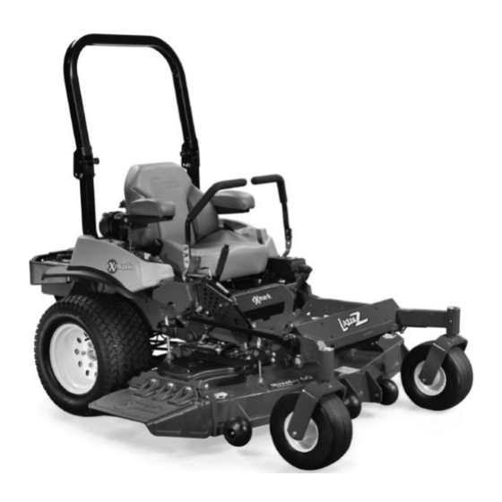
- Page 1 LAZER Z MODELS ® For Serial Nos. 790,000 & Higher Part No. 4500-471 Rev. A...
- Page 2 Replacements may be ordered through the engine manufacturer. Exmark reserves the right to make changes or add improvements to its products at any time without incurring any obligation to make such changes to products manufactured previously.
-
Page 3: Introduction
All Exmark parts are thoroughly tested and inspected before leaving the factory, however, attention is required on your part if you are to obtain the fullest measure of satisfaction and performance. -
Page 4: Table Of Contents
Contents Introduction ... 3 Safety ... 5 Safety Alert Symbol ... 5 Safe Operating Practices ... 5 Safety and Instructional Decals ... 10 Specifications ... 14 Model Numbers ... 14 Systems ... 14 Dimensions... 16 Torque Requirements ... 18 Product Overview ... 18 Operation ... -
Page 5: Safety
• Evaluate the terrain to determine what accessories and attachments are needed to properly and safely perform the job. Only use accessories and attachments approved by Exmark. • Wear appropriate clothing including safety glasses, substantial footwear, long trousers, and hearing protection. - Page 6 Safety DANGER In certain conditions gasoline is extremely flammable and vapors are explosive. A fire or explosion from gasoline can burn you, others, and cause property damage. • Fill the fuel tank outdoors in an open area, when the engine is cold. Wipe up any gasoline that spills.
- Page 7 CAUTION Fuel tank vent is located inside the roll bar tube. Removing or modifying the roll bar could result in fuel leakage and violate emissions regulations. • Do Not remove roll bar. • Do Not weld, drill, or modify roll bar in any way.
-
Page 8: Slope Operation
Safety • Be aware of the mower discharge path and direct discharge away from others. • Do Not operate the mower under the influence of alcohol or drugs. • Use extreme care when loading or unloading the machine into a trailer or truck. •... -
Page 9: Maintenance And Storage
WARNING There is no rollover protection when the roll bar is down. Wheels dropping over edges, ditches, steep banks, or water can cause rollovers, which may result in serious injury, death or drowning. • Keep the roll bar in the raised and locked position and use seat belt. -
Page 10: Safety And Instructional Decals
1-403005 • New safety signs may be obtained from your authorized Exmark equipment dealer or distributor or from Exmark Mfg. Co. Inc. • Safety signs may be affixed by peeling off the backing to expose the adhesive surface. Apply only to a clean, dry surface. Smooth to remove any air bubbles. - Page 11 107-2102 107-2112 109-3148 109-7232 1. Fast 3. Neutral 2. Slow 4. Reverse 109-7330 109-7929 Safety...
- Page 12 Safety 109-8483 1. Throttle–fast 3. Choke–on 2. Throttle–slow 4. Choke–off 109-9361 Deck Drive Belt Routing 109-9477 116-0090 116-0157 1. See Operator’s manual 116-0165 116-0205...
- Page 13 116-0211 116-0752 1. Latch 2. Unlatch Message Display 1. Fuel 2. Empty 3. Half 4. Full 5. Battery PTO Switch Symbols 1. PTO–disengage 109-7069 Safety 6. Hour meter 7. PTO 8. Parking brake 9. Neutral 10. Operator presence switch 2. PTO–engage...
-
Page 14: Specifications
Specifications Specifications Model Numbers Serial Nos: 790,000 and Higher LZZ23KC486; LZZ23KA526; LZZ23KC526; LZZ27KC526; LZZ27KC606; LZZ29KA606; LZZ34KA606; LZZ34KA726 Systems Engine • Engine Specifications: See your Engine Owner’s Manual • RPM: Full Speed: 3750 ±50 RPM (PTO not engaged) Idle: 1500 RPM Fuel System •... -
Page 15: Hydrostatic Ground Drive System
– 60 and 72 inch decks: ◊ 16cc Parker axial piston pump ◊ 280cc Ross geroler motor • Hydraulic Oil Type: Exmark Premium Hydro oil. • Hydraulic Oil Capacity: 52 oz (1.5 L) per side • Hydraulic Filter: P/N 116-0164 •... -
Page 16: Dimensions
Specifications Cutting Deck • Cutting Width: – 48 inch Deck: (121.9 cm) – 52 inch Deck: (132.1 cm) – 60 inch Deck: (152.4 cm) – 72 inch Deck: (182.9 cm) • Discharge: Side • Blade Size: (3 ea.) – 48 inch Deck: 16.25 inches (41.3 cm) –... -
Page 17: Curb Weight
Tread Width: (Center to Center of Tires, Widthwise) 48 inch Deck Drive Wheels 36.2 inches (91.9 cm) Caster Wheels 32.8 inches (83.3 cm) 60 inch Deck Drive Wheels 41.6 inches (105.7 cm) Caster Wheels 39.5 inches (100.3 cm) Wheel Base: (Center of Caster Tire to Center of Drive Tire) 48 inch 52 inch... -
Page 18: Torque Requirements
Product Overview *60 inch units which already have an under toe board mount weight as standard requires 116-1238 front toe board top mount kit instead of 116-1173. Torque Requirements Bolt Location Torque Blade Drive Sheave 90-110 ft-lb (122-149 N-m) Mounting Nut Cutter Housing Spindle 160-185 ft-lb (217-251 N-m) -
Page 19: Operation
Operation Note: Determine the left and right sides of the machine from the normal operating position. Controls Motion Control Levers The motion control levers located on each side of the console control the forward and reverse motion of the machine. Moving the levers forward or backward turns the wheel on the same side forward or reverse respectively. -
Page 20: Ignition Switch
Operation Note: The LCD indicator appears in the message display on the RH console when the park brake is engaged (see Figure 9). Pull the lever up and rearward to engage the brake. Depress the release button and push downward to disengage the brake. -
Page 21: Drive Wheel Release Valves
Fuel Shut-Off Valve Located behind and below the seat. The fuel shut-off valve is used to shut off the fuel when the machine will not be used for a few days, during transport to and from the jobsite, and when parked inside a building. -
Page 22: Deck Lift Pedal
Operation Deck Lift Pedal Located at the right front corner of the floor pan. Push the pedal forward with your foot to raise the cutting deck. Allow the pedal to move rearward to lower the cutting deck to the cut height that has been set. -
Page 23: Starting The Engine
the roll bar may need to be pushed forward or pulled rearward to get both knobs fully engaged (see Figure 13). Figure 13 1. Engaged 2. Partially engaged — Do Not operate with ROPS in this condition. Important: Always use the seat belt with the roll bar in the operate (raised) position. -
Page 24: Stopping The Engine
Operation Stopping the Engine 1. Bring the unit to a full stop. 2. Disengage the PTO. 3. Move the motion control levers out to the neutral lock position. 4. Engage the parking brake. 5. Place the throttle midway between the “SLOW” and “FAST”... -
Page 25: Adjusting The Cutting Height
Figure 15 1. Front of Unit 3. Neutral 2. Forward 4. Reverse Driving in Reverse 1. Move the motion control levers inward to the neutral operate position. 2. To move rearward in a straight line, move both levers rearward with equal pressure. To turn left or right, release pressure on the motion control lever toward the desired turn direction. -
Page 26: Transporting
Operation Figure 17 For cutting heights above 3.5 inches (90 mm) use the bottom hole. The rollers will still be effective against scalping. 1. Anti-scalp roller 2. Cutting height mounting bracket For Maximum Deck Flotation, place the rollers one hole position lower. Rollers should maintain 1/4 inch (6.4 mm) clearance to the ground. -
Page 27: Loading A Unit
WARNING Loading a unit on a trailer or truck increases the possibility of backward tip-over. Backward tip-over could cause serious injury or death. • Use extreme caution when operating a unit on a ramp. • Use only a single, full width ramp; Do Not use individual ramps for each side of the unit. -
Page 28: Maintenance
Maintenance Maintenance Note: Determine the left and right sides of the machine from the normal operating position. WARNING While maintenance or adjustments are being made, someone could start the engine. Accidental starting of the engine could seriously injure you or other bystanders. Remove the key from the ignition switch, engage parking brake, and pull the wire(s) off the spark plug(s) before you do any... -
Page 29: Periodic Maintenance
Maintenance Service Maintenance Procedure Interval • Change the hydraulic filter and fluid. • Check the wheel hub slotted nut torque specifications. Every 500 hours • Check the wheel lug nuts. • Check the park brake adjustment. • Grease the deck and pump idler pivots. Yearly •... -
Page 30: Check Mower Blades
Always install the original Exmark blades, blade bushings, and blade bolts as shown. Check Safety Interlock System... -
Page 31: Check Rollover Protections Systems (Roll Bar) Knobs
1/2 second has elapsed whether operator is on seat or not. Note: If machine does not pass any of these tests, do not operate. Contact your authorized EXMARK SERVICE DEALER. Important: It is essential that operator safety mechanisms be connected and in proper operating condition prior to use for mowing. -
Page 32: Change Engine Oil
Note: The oil level on the dipstick will be incorrect if the oil is checked when the unit is hot. 7. If the dipstick oil level is at the “add” mark add Exmark Premium Hydro oil. 8. Replace hydraulic reservoir cap and tighten until snug. Do Not overtighten. -
Page 33: Check Condition Of Belts
6. Pack the bearings with a NGLI grade #1 multi-purpose grease. 7. Insert one bearing, one new seal into the wheel. Note: Seals (Exmark P/N 103-0063) must be replaced. 8. If the axle assembly has had both spacer nuts removed (or broken loose), apply a thread locking adhesive to one spacer nut and thread onto the axle with the wrench flats facing outward. -
Page 34: Lubricate Brake Handle Pivot
Change Hydraulic System Filter and Fluid Service Interval: Every 500 hours Note: Only use Exmark Hydro Filter–Part No. 116-0164 for summer or winter. 1. Stop engine, wait for all moving parts to stop, and remove key. Engage parking brake. -
Page 35: Wheel Hub - Slotted Nut Torque Specification
7. Before installing the new filters, apply a thin coat of Exmark Premium Hydro oil on the surface of the two rubber seals. 8. Install the new filters and torque to 14 ft-lb (19 N-m). 9. Fill the hydraulic system as stated in Check Hydraulic Oil Level section. -
Page 36: Thread Locking Adhesives
Maintenance 3. If any breaks in the screen or welds are observed, replace arrester. 4. If plugging of the screen is observed, remove arrester and shake loose particles out of the arrester and clean screen with a wire brush (soak in solvent if necessary). - Page 37 Figure 25 1. Foot lever 3. Transport lock 2. Cut of height pin 6. Insert the height adjustment pin into the 3 inch (7.6 cm) cutting height location. 7. Release the transport lock and allow the deck to lower to the cutting height. 8.
-
Page 38: Deck Removal
Maintenance Figure 28 1. Single point height adjustment bolt 2. Front height-of-cut plate mounting bolt 3. Rear height-of-cut plate mounting bolt 15. To adjust the single point system, first loosen the front and rear height-of-cut plate mounting bolts. 16. If the deck is too low, tighten the single point adjustment bolt by rotating it clockwise. -
Page 39: Pump Drive Belt Tension
7. Raise the front of the machine and slide the deck left or right to remove. 8. Lower the front of the machine. Pump Drive Belt Tension Self-tensioning - No adjustment necessary. Deck Belt Tension Self-tensioning - No adjustment necessary. Adjusting the Parking Brake Service Interval: After the first 100 hours Every 500 hours thereafter... -
Page 40: Electric Clutch Adjustment
Maintenance 16. Install the rear tires and torque lug nuts to 90-95 ft-lb (122-129 N-m). 17. Remove jack stands. Electric Clutch Adjustment No adjustment necessary. Motion Control Linkage Adjustment Located on either side of the fuel tank, below the seat are the pump control linkages. -
Page 41: Motion Control Neutral Lock Pivot Adjustment
Figure 32 RH Motion Control Shown 1. Torque nyloc nut to 200 in-lb (16.7 ft-lb). Bolt must protrude past end of nyloc nut after torque. A T-40 Torx bit will be necessary to hold the stud from turning. 2. Most resistance (firmest feel) 3. -
Page 42: Caster Pivot Bearings Pre-Load Adjustment
Maintenance 2. Slide the cover plate backward or forward to adjust the travel of the lever and tighten the screws. 3. Drive the machine and check the full forward tracking. 4. Repeat steps 1 through 3 until desired tracking is obtained. Figure 35 RH Motion Control Shown 1. -
Page 43: Cleaning
Cleaning Clean Engine and Exhaust System Area Service Interval: Before each use or daily (May be required more often in dry or dirty conditions.) CAUTION Excessive debris around engine cooling air intake and exhaust system area can cause engine, exhaust area, and hydraulic system to overheat which can create a fire hazard. -
Page 44: Waste Disposal
Maintenance CAUTION Raising the mower deck for service or maintenance relying solely on mechanical or hydraulic jacks could be dangerous. The mechanical or hydraulic jacks may not be enough support or may malfunction allowing the unit to fall, which could cause injury. Do Not rely solely on mechanical or hydraulic jacks for support. -
Page 45: Troubleshooting
Troubleshooting Important: It is essential that all operator safety mechanisms be connected and in proper operating condition prior to mower use. When a problem occurs, do not overlook the simple causes. For example: starting problems could be caused by an empty fuel tank. The following table lists some of the common causes of trouble. - Page 46 Troubleshooting Problem Engine loses power Mower pulls left or right (with levers fully forward) Machine does not drive Uneven cutting height. Abnormal vibration Blades do not rotate. Possible Cause 1. Engine load is excessive 2. Air cleaner is dirty. 3. Oil level in the crankcase is low. 4.
-
Page 47: Schematics
Schematics Electrical Diagram PINK BLACK BROWN PINK GREEN Schematics WHITE BROWN YELLOW BLUE PINK BLACK GREEN GRAY VIOLET ORANGE PINK... -
Page 48: Electrical Logic Schematic
Schematics Electrical Logic Schematic KEY_S KEY_A SEAT BRAKE NEUTRAL FUEL START_RELAY MAGNETO FUEL_SOLENOID GROUND... - Page 49 Schematics Hydraulic Diagram...
- Page 50 Exmark dealer. The warranty period commences upon the date of the original retail purchase. Commercial Warranty Conditions This warranty applies to Exmark Lazer Z and Lazer Z AS turf equipment sold in the U.S. or Canada for a period of three years for commercial usage.
- Page 51 Notes:...
- Page 52 Notes:...
-
Page 53: Service Record
Service Record Date: Description of Work Done: Service Done By:... - Page 56 SEE EXMARK’S COMPLETE LINE OF ACCESSORIES AND OPTIONS MID-MOUNT RIDING ACCESSORIES AND OPTIONS CUSTOM RIDE SEAT SUSPENSION SYSTEM FULL SUSPENSION SEAT DECK LIFT ASSIST KIT HITCH KIT LIGHT KIT V POWER PORT MICRO-MULCH SYSTEM OUT-FRONT RIDING ACCESSORIES AND OPTIONS CUSTOM RIDE SEAT SUSPENSION SYSTEM...
Need help?
Do you have a question about the 000 & Higher and is the answer not in the manual?
Questions and answers