Table of Contents
Advertisement
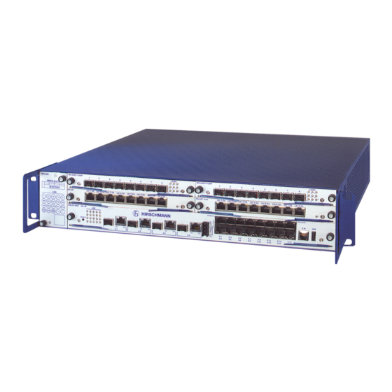
User Manual
Installation
Modular Industrial ETHERNET Backbone Switch
MACH 4002 Family
M4-AIR
M4-FAST 8SFP
1
MEDIA SLOTS
3
4
1
2
SLOT.PORT
1
LS
DA
M4-8TP-RJ45
LED
P
P1
P2
P3
P4
RM
RL1
RL2
FAN
RUN
MACH 4002 48+4G
LED
L/D
FDX 1000
AN TP/FO
RING
LED
PORT STBY
2
1
TEST
SELECT
MACH 4002
Release 1.0 10/05
2
3
4
5
6
7
2
3
4
5
6
DA LS
7
DA LS
LS
DA
LS
DA LS
DA LS
DA LS
LS
DA
LS
DA
5.1
5.2
LS/DA
M4-FAST 8SFP
8
1
1
4
7
2
5
8
P
3
6
8
1
DA
LS
DA
LS
M4-8TP-RJ45
P
LS/DA 6.1
RL1
RL2
LS
DA
LS
DA
6.1
5.3
5.4
6.2
2
3
4
5
6
7
8
2
3
4
5
6
DA LS
7
DA LS
8
DA
LS
DA LS
DA LS
DA LS
6.16 LS/DA
6.3
6.5
6.7
6.9
6.11
6.13
6.15
6.4
6.6
6.8
6.10
6.12
6.14
6.16
Technical support
HAC-Support@hirschmann.de
LS/DA
1
4
7
2
5
8
P
3
6
DA
R
V.24
USB
Advertisement
Table of Contents

Subscribe to Our Youtube Channel
Related Manuals for Hirschmann MACH 4002 Family


Summary of Contents for Hirschmann MACH 4002 Family
-
Page 1: User Manual
User Manual Installation Modular Industrial ETHERNET Backbone Switch MACH 4002 Family LS/DA LS/DA M4-AIR M4-FAST 8SFP M4-FAST 8SFP MEDIA SLOTS SLOT.PORT DA LS DA LS DA LS DA LS DA LS DA LS DA LS DA LS DA LS DA LS... - Page 2 The performance features described here are binding only if they have been expressly guaranteed in the contract. This publication has been created by Hirschmann Automation and Control GmbH according to the best of our knowledge. Hirschmann reserves the right to change the contents of this manual without prior notice.
-
Page 3: Table Of Contents
Content Safety instructions About this manual Legend Description of the device Basic device MACH 4002 48+4G Voltage supply 1.2.1 Power supply on back of device 1.2.2 M4-POWER power unit chassis Fan plug-in unit M4-AIR Integated Basic Board 1.4.1 4 Gigabit ETHERNET ports (Combo) 1.4.2 16 Fast ETHERNET ports Media modules 1.5.1 Fast ETHERNET ports... - Page 4 Disassembling the device 2.4.1 Disassembling the media modules 2.4.2 Disassembling the SFP modules Technical data General data Interfaces EMV and stability Power consumption/power output Scope of delivery Order numbers/Product name Asseccories Further support MACH 4002 Release 1.0 10/05...
-
Page 5: Safety Instructions
Safety instructions This manual contains instructions which must be observed to ensure your own personal safety and to avoid damage to devices and machinery. Certified usage Please observe the following: The device may only be employed for the purposes described in the catalog and technical description, and only in conjunction with external devices and components recommended or approved by Hirschmann. -
Page 6: Ambient Conditions
V Beware of possible short circuits when connecting a cable section with conductive shielding braiding. Housing Only technicians authorized by Hirschmann are permitted to open the housing. The device is grounded via the power supply connections. V Make sure that the electrical installation meets local or nationally ap- plicable safety regulations. -
Page 7: General Safety Instructions
trained or directed or authorized to switch on and off, to ground and to label power circuits and devices or systems in accordance with current safety engineering standards; trained or directed in the care and use of appropriate safety equipment in accordance with the current standards of safety engineering;... - Page 8 31/EEC and 93/68/EEC). In accordance with the above-named EU directives, the EU conformity declaration will be at the disposal of the relevant authorities at the follo- wing address: Hirschmann Automation and Control GmbH Stuttgarter Straße 45-51 D-72654 Neckartenzlingen Germany Phone ++49 7127 14 1480 The product can be used in living areas (living area, place of business, small business) and in industrial areas.
- Page 9 Warning! This is a class A device. This device can cause interference in living areas, and in this case the operator may be required to take appropriate measures. The assembly guidelines provided in these instructions must be strictly adhered to in order to observe the EMC value limits. FCC note: Appropriate testing has established that this device fulfills the require- ments of a class A digital device in line with part 15 of the FCC...
-
Page 10: About This Manual
About this manual The following manuals are included as PDF files on the enclosed CD ROM: User manual “Installation” User manual “Basic configuration” User manual “Redundancy configuration” User manual "Router configuration" Reference manual “Web-based Interface” and Reference manual “Command Line Interface” If you use Network Management Software HiVision you have further opportunities to: have an event logbook. -
Page 11: Description Of The Device
Description of the device The modular, industry-compatible MACH 4002 Gigabit ETHERNET system is used as an industrial backbone system, and also in applications with high data volumes, such as Video over IP. The MACH 4002 is a modular, industry-compatible Gigabit ETHERNET system in a 19"... -
Page 12: Basic Device Mach 4002 48+4G
Web-based interface Command Line Interface - CLI SNMP 802.1x port authentication Real Time Clock Routing Access Control List ACL In addition, to the MACH family backbone switches, the RS20/RS30 Open Rail range of switches and the MICE family, the BAT wireless transmission system, the EAGLE security system, and products for the LION control room, provides continuous communication across all levels of the company. - Page 13 The MACH 4002 48+4G chassis are 2 height modules high (approx. 88 mm) and, depending on the media modules that are connected, they provide you with up to 48 Fast ETHERNET and 4 Gigabit ETHERNET ports. The chassis differ as to the range of functions of the software (see table “Order numbers/Product name”...
-
Page 14: Voltage Supply
The device conforms to the specifications of the standards ISO/IEC 8802-3u 100BASE-TX/-1000BASE-T, ISO/IEC 8802-3 100BASE-FX and ISO/IEC 8802-3 1000BASE-SX/LX. Voltage supply On the back of the device there is a slot for a power supply unit (AC or DC) and two inputs for the redundant power supply via the M4-POWER power unit chassis. -
Page 15: Fan Plug-In Unit M4-Air
You connect the M4-POWER power unit to the M4-POWER connection on the back of the MACH 4002 device using exclusively the power supply cable supplied with the M4-P-xx slide-in power units. Power unit 1 Power unit 2 Power unit 3 Fig. -
Page 16: Integated Basic Board
Integated Basic Board The integrated Basic Board provides you with 16 Fast ETHERNET and 4 Gigabit ETHERNET ports. MACH 4002 48+4G LS/DA 6.1 6.16 LS/DA V.24 SELECT 6.11 6.13 6.15 6.10 6.12 6.14 6.16 1.4.1 4 Gigabit ETHERNET ports (Combo) There are four Gigabit ETHERNET ports (ports number 5.1 to 5.4) for connecting power unit segments on the left side of the Basic Board. -
Page 17: Media Modules
Media modules Fig. 3: SFP- and TP media module 1.5.1 Fast ETHERNET ports U M4-8TP-RJ45 The M4-8TP-RJ45 media module provides you with eight 10/100BASE-TX ports (RJ-45 connections) for connecting power unit segments. DA LS DA LS DA LS DA LS DA LS M4-8TP-RJ45 U M4-FAST 8-SFP... -
Page 18: Assembly And Startup Procedure
Assembly and startup procedure The device has been developed for practical application in a harsh industrial environment. Accordingly, the installation process has been kept simple. On delivery, the device is ready for operation. The following procedure is appropriate for assembly: Unpacking and checking Assembling the media modules Assembling the SFP modules (if required) -
Page 19: Assembling The Sfp Modules (If Required)
Step 1 Step 2 Step 3 V Please observe the “ESD guidelines” on page 8 “ and the “Safety instruc- tions” on page 5ff. V Close the whole of the front surface beside the media modules with pa- nels. This guarantees optimum shielding and convection. The slots for the media modules function identically. -
Page 20: Assembling The Power Supply Unit On The Back Of The Device
2.1.4 Assembling the power supply unit on the back of the device V Remove the covering panel. V Slide the power supply unit all the way into the chassis along the mounting rails above and below. V Make sure that there is a good connection between the multiple plug of the slide-in power unit and the female multipoint of the system bus. -
Page 21: Setup Or Installation Of The Device In A 19" Rack
2.1.6 Setup or installation of the device in a 19" rack U Setup Using the basic device as a desktop device: V Attach the rubber foot delivered with the device to its underside. – First remove the protective film from the rubber foot. –... -
Page 22: Connecting The Terminal Block For Signal Contact
2.1.9 Connecting the terminal block for signal contact Fig. 4: 4-pin signal contact The signal contact (“FAULT”) monitors proper functioning of the device, thus enabling remote diagnostics. You can specify the type of function monitoring in the Management. You can also use the Management to set the signal contact manually and thus control external devices. -
Page 23: 10Connecting The Supply Voltage, Startup Procedure
V Mount the terminal block for both the signal contacts on the front of the device. Make sure that the snap lock snaps into place. 2.1.10 Connecting the supply voltage, startup procedure V The devices may only be connected to the supply voltage shown on the type plate. -
Page 24: 11Connecting The Data Lines
2.1.11 Connecting the data lines The ports of the device enable you to connect terminal devices or further network segments via twisted pair or F/O cable. 10/100 Mbit/s twisted pair connection 10/100 Mbit/s ports (RJ45 sockets) enable the connection of terminal devices or independent network segments in compliance with the IEEE 802.3 100BASE-TX / 10BASE-T standards. -
Page 25: (If Required)
BI_DC- Pin 8 BI_DC+ Pin 7 BI_DA- Pin 6 BI_DD- Pin 5 BI_DD+ Pin 4 BI_DA+ Pin 3 BI_DB- Pin 2 BI_DB+ Pin 1 Fig. 7: Pin assignment of a 1000 MBit/s twisted pair interface 100 Mbit/s F/O connection 100 MBit/s F/O ports (SFP slots) enable the connection of terminal devices or independent network segments in compliance with the IEEE 802.3 100BASE-FX standard. -
Page 26: Displays
If required, the fan plug-in unit can be replaced. It may be replaced by an electrician without turning off the device. Depending on the ambient tempe- rature the MACH 3000 can be operated up to one or two minutes with one dissasembled fan. -
Page 27: Device Status
Device status These LED's provide information about conditions which affect the ope- ration of the whole device. P- Power (green LED) Meaning lit green internal supply voltage on not lit internal supply voltage too low P1 - Power 1 (green LED) Meaning lit green supply voltage 1 at the power supply plug-in unit on... - Page 28 AIR - fan overall status Meaning (green LED) lit green The existence of a fan slot but no fan indicates an error. not lit The existence of a fan slot and at least one fan indicates an error, or there is no fan slot. RUN - BOOT/RUN Meaning (green LED)
-
Page 29: Port Status
LED TEST - LED test Meaning (green LED) lit green The test of the LEDs status, display status and port status is active. The status LED „RM“ flashes green/yellow. The status LED "FAULT" flashes red. The display status LEDs blink green. The port status LEDs of the media modules blink green/ yellow. - Page 30 These LEDs display port-related information. The following LEDs are available for each port: two single-color LEDs (for each of the 4 combo ports of the Basic Boards) one two-color LED (for each of the 8 ports of the media modules and for each of the 16 TP ports of the Basic Boards) Set the contents of the information with the button on the basic module.
-
Page 31: Carrying Out Basic Settings
Carrying out basic settings IP addresses must be entered when the device is installed for the first time. The device provides 6 options for configuring the IP addresses: Entry via the V.24 connection. Entry by HiDiscovery protocol Configuration via BOOTP Configuration via DHCP Configuration via DHCP Option 82 The AutoConfiguration Adapter... - Page 32 V.24 interface (external management) A serial interface is provided on the RJ11 socket (V.24 interface) for the local connection of an external management station (VT100 terminal or PC with appropriate terminal emulation). This makes it possible to esta- blish a connection to the Command Line Interface CLI and to the system monitor.
-
Page 33: Disassembling The Device
Disassembling the device 2.4.1 Disassembling the media modules Step 2 Step 1 Step 3 V Please notice the “ESD guidelines” on page 8 “ and the “Safety instruc- tions” on page 5ff. V Lever the selected media module from the slot by pulling the blue insertion catches (see Fig., steps 1 and 2). -
Page 34: Technical Data
Technical data General data Dimensions MACH 4002 W x H x D: 480 mm x 88 mm x 435 mm Assembly MACH 4002 19" rack M4-POWER 19" rack Weight MACH 4002 7.5 kg Voltage supply MACH 4002 M4-S-xx power supply or power unit chassis M4-POWER with M4-P-xx power supply, please order separately Operating voltage M4-S-AC/DC 300W... -
Page 35: Emv And Stability
Interfaces Interface Design MACH 4002 signal contact 4-pin pluggable terminal block V.24 interface 1 x RJ11 socket USB interface to connect an AutoConfiguration Adapter ACA 21-USB EMV and stability EMV interference proof EN 61000-4-2 Discharge of static electricity Contact discharge: test level 3 6 kV Air discharge: test level 3 8 KV... -
Page 36: Power Consumption/Power Output
Product Fiber System Expansion Fiber data Wave code attenuation length M-FAST SFP-... -MM/LC MM 1310 nm 50/125 µm 0-11 dB 0-5 km 1.0 dB/km, 800 MHz*km -MM/LC MM 1310 nm 62.5/125 µm 0-8 dB 0-4 km 1.0 dB/km, 500 MHz*km -SM/LC SM 1310 nm 9/125 µm... -
Page 37: Scope Of Delivery
Name Power consumption Power output M-FAST SFP-MM/LC 1.0 W 3.4 Btu (IT)/h M-FAST SFP-SM/LC 1.0 W 3.4 Btu (IT)/h M-FAST SFP-SM+/LC 1.0 W 3.4 Btu (IT)/h M-FAST SFP-LH/LC 1.0 W 3.4 Btu (IT)/h M4-8TP-RJ45 2.0 W 7.0 Btu (IT)/h M4-FAST 8SFP 15.0 W 52.0 Btu (IT)/h Scope of delivery... - Page 38 Product name Description Order no. M4-S-48VDC 300W Slide-in 48VDC power unit, single-current, 943 872-001 for switch chassis (2 connections coupled via diodes, one DC/DC converter) M4-P-AC/DC 300W Slide-in AC power unit (300 W) for power unit chassis 943 875-001 M4-P-24VDC 300W Slide-in 24VDC power unit, single-current, 943 876-001 for power unit chassis (2 connections coupled...
- Page 39 FCC 47 CFR Part 15:2003 Code of Federal Regulations Germanischer Lloyd Rules for Classification and Construction VI - 7 - 3 Part 1, Ed. 2003 cUL 508:1998 Safety for Industrial Control Equipment cUL 60950 Safety for Information Technology Equipment Tab. 4: List of based specifications and standards Certified devices are marked with a certification identifier.
- Page 40 MACH 4002 Release 1.0 10/05...
- Page 41 Further support Technical questions and training courses In the event of technical queries, please talk to the Hirschmann contract partner responsible for looking after your account or directly to the Hirschmann office. You can find the addresses of our contract partners on the Internet: http://www.hirschmann.com Our support line is also at your disposal:...
- Page 42 !'#!" #...
Need help?
Do you have a question about the MACH 4002 Family and is the answer not in the manual?
Questions and answers