Table of Contents
Advertisement
User Manual
Installation
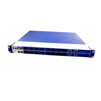
Industrial Ethernet Ruggedized Switch
MACH 1000 Family
USB
V.24
LS
3
P
RM
StandBy
R1 R2
FAULT
MACH 1020
5
MACH 1020
V.24
USB
LS
1
3
P
RM
StandBy
2
R1 R2
FAULT
MACH 1030
5
MACH 1030
USB
USB
V.24
V.24
1
3
RM
RM
StandBy
StandBy
P
P
2
R1 R2
R1 R2
FAULT
FAULT
MACH 1000
5
MACH 1032
USB
USB
V.24
V.24
LS
1
1
3
3
P
P
RM
RM
StandBy
StandBy
LS
2
2
R1 R2
R1 R2
FAULT
FAULT
MACH 1000
5
5
MACH 1132
Installation MACH 1000
Release 04 12/2015
DA
LS
DA
7
8
4
6
9
10
DA
LS
DA
4
7
8
6
9
10
4
7
8
6
10
9
DA
LS
DA
7
8
4
4
DA
6
6
9
10
12
11
15
16
LS
DA
LS
DA
13
14
17
18
11
12
15
16
LS
DA
LS
DA
13
14
17
18
11
12
15
16
LS
DA
LS
DA
13
14
17
18
11
12
15
16
LS
DA
LS
DA
13
14
17
18
P
RM
StandBy
1
3
5
7
9 11 13 15 17 19 21 23
R1 R2
2
4
6
8 10 12 14 16 18 20 22 24
FAULT
ETHERNET Service Port
https://hirschmann-support.belden.eu.com
LS
DA
LS
DA
23
24
19
20
22
25
26
21
LS
DA
LS
DA
19
20
23
24
26
21
22
25
19
20
23
24
25
26
21
22
22
20
23
24
19
21
22
25
26
Technical Support
Advertisement
Table of Contents

Related Manuals for Hirschmann MACH 1020


Summary of Contents for Hirschmann MACH 1020
-
Page 1: User Manual
User Manual Installation Industrial Ethernet Ruggedized Switch MACH 1000 Family V.24 StandBy R1 R2 FAULT MACH 1020 MACH 1020 V.24 StandBy R1 R2 FAULT MACH 1030 MACH 1030 V.24 V.24 StandBy StandBy R1 R2 R1 R2 FAULT FAULT MACH 1000 MACH 1032 V.24... - Page 2 In addition, we refer to the conditions of use specified in the license contract. You can get the latest version of this manual on the Internet at the Hirschmann product site (www.hirschmann.com). Hirschmann Automation and Control GmbH Stuttgarter Str.
-
Page 3: Table Of Contents
Contents Safety instructions About this Manual Legend Description General device description Combination options Description of the device variants 1.3.1 Front view of the MACH 1000 with 2 Gigabit ports 1.3.2 Front view of the MACH 1000 with 4 Gigabit ports (SFP) 1.3.3 Front view of the MACH 1000 with 4 Gigabit ports (2 x SFP and 2 x RJ45) - Page 4 2.2.1 Connecting the voltage supply terminals (power supply units “C” and “G”) 2.2.2 Connecting the plugged voltage supply (power supply units “L” and “M”) 2.2.3 Connecting the signal contact Installing and grounding the device 2.3.1 Mounting in a switch cabinet 2.3.2 Vertical mounting on the wall 2.3.3 Grounding the device Operating the device...
-
Page 5: Safety Instructions
Certified usage Use the product only for the application cases described in the Hirschmann product information, including this manual. Operate the product only according to the technical specifications. See “Technical data” on page 55. Connect to the product only components suitable for the requirements of the specific application case. -
Page 6: Installation Site Requirements
Installation site requirements Install this device solely in a switch cabinet or in an operating site with restricted access, to which maintenance staff have exclusive access. Mount the device horizontally in a cabinet or vertically on a flat surface. Operating the device as a table unit is inadmissible. - Page 7 National and international safety regulations Verify that the electrical installation meets local or nationally applicable safety regulations. Grounding the device The device is grounded via the separate grounding screw on the back of the device. Use a wire diameter for the ground conductor that is no smaller than the diameter of the supply voltage connection, however of at least 1.0 mm²...
- Page 8 Supply voltage The supply voltage is electrically isolated from the housing. Connect only a supply voltage that corresponds to the type plate of your device. Every time you connect the electrical conductors, make sure that the following requirements are met: ...
- Page 9 The cables used are permitted for the temperature range of the application case. Relevant for North America: For use in Class 2 circuits, the copper wire conforms to class 1, 60/75 °C or 75 °C. Verify that the electrical installation meets locally or nationally applicable safety regulations.
- Page 10 Use in Hazardous Locations Relevant for use in explosion hazard areas of the Hazardous Locations category (Class I, Division 2): This device is only suitable for use in explosion hazard areas of category “Class I, Division 2, Groups A, B, C, D” or for use in non-explosion hazard areas.
- Page 11 Installation MACH 1000 Release 04 12/2015...
- Page 12 Installation MACH 1000 Release 04 12/2015...
- Page 13 In accordance with the above-named EU directive(s), the EU conformity declaration will be at the disposal of the relevant authorities at the following address: Hirschmann Automation and Control GmbH Stuttgarter Str. 45-51 72654 Neckartenzlingen Germany Tel.: +49 1805 141538...
- Page 14 FCC note: This device complies with part 15 of the FCC rules. Operation is subject to the following two conditions: (1) this device may not cause harmful interference; (2) this device must accept any interference received, including interference that may cause undesired operation. Appropriate testing has established that this device fulfills the requirements of a class A digital device in line with part 15 of the FCC regulations.
-
Page 15: About This Manual
About this Manual The “Installation” user manual contains a device description, safety instructions, a description of the display, and the other information that you need to install the device. The following manuals are available as PDF files on the CD/DVD supplied: ... -
Page 16: Description
Description General device description The MACH 1000 devices are designed for the special requirements of industrial automation. They meet the relevant industry standards, provide very high operational reliability, even under extreme conditions, and also long-term reliability and flexibility. The devices allow you to set up switched industrial Ethernet networks that conform to the IEEE 802.3 standard. -
Page 17: Combination Options
You will find these manuals as PDF files on the enclosed CD/DVD, or you can download them from the Internet on the Hirschmann product pages (www.hirschmann.com). The Hirschmann network components help you ensure continuous communication across all levels of the company. Combination options The product designation of your device is made from combining the desired product characteristics in accordance with the following table. - Page 18 Position Characteristic Ident. Property 9 to 10 10/100/1000 Mbit/s ports Not present (in MAR1020) 1 + 2 or 1 to 4 2 × combo port (SFP slot: 100/1000 Mbit/s, alternatively twisted pair RJ45 socket: 10/100/1000 Mbit/s) 2 × 2 Gigabit Ethernet ports SFP 1000 Mbit/s 2 ×...
- Page 19 Position Characteristic Ident. Property Approvals CE, UL 508, ISA 12.12.01- Class I, Div. 2, GL, IEC 61850, IEEE 1613 Substation, EN 50121-4 Railway (along track), NEMA TS2 CE, UL 508, ISA 12.12.01- Class I, Div. 2, EN 50121-4 railway (along track), NEMA TS2, EN 50155 railway (train) Software variant Professional...
-
Page 20: Description Of The Device Variants
Description of the device variants The MAR1020-..., MAR1022-..., MAR1120-... and MAR1122-... device variants are MACH 1000 Ruggedized Switches without Gigabit ports and, depending on the requirements, a selectable number (up to 24) of Fast Ethernet ports (10/100 Mbit/s). You can choose the media for the Fast Ethernet ports 1 to 24 in pairs. -
Page 21: Front View Of The Mach 1000 With 2 Gigabit Ports
1.3.1 Front view of the MACH 1000 with 2 Gigabit ports MACH 1000 V.24 StandBy R1 R2 FAULT MACH 1000 Figure 1: 1 - LED display elements 2 - USB interface 3 - V.24 connection for external management 4 - See following table, column 1 5 - See following table, column 2 Gigabit Ethernet Fast Ethernet... -
Page 22: Front View Of The Mach 1000 With 4 Gigabit Ports (Sfp)
1.3.2 Front view of the MACH 1000 with 4 Gigabit ports (SFP) MACH 1000 V.24 V.24 StandBy StandBy R1 R2 R1 R2 FAULT FAULT MACH 1000 Figure 2: 1 - LED display elements 2 - USB interface 3 - V.24 connection for external management 4 - See following table, column 1 5 - See following table, column 2 Gigabit Ethernet... -
Page 23: Front View Of The Mach 1000 With 4 Gigabit Ports (2 X Sfp And 2 X Rj45)
1.3.3 Front view of the MACH 1000 with 4 Gigabit ports (2 x SFP and 2 x RJ45) MACH 1000 V.24 V.24 StandBy StandBy R1 R2 R1 R2 FAULT FAULT MACH 1000 Figure 3: 1 - LED display elements 2 - USB interface 3 - V.24 connection for external management 4 - See following table, column 1 5 - See following table, column 2... -
Page 24: Front View Of The Mach 1000 With Poe
1.3.4 Front view of the MACH 1000 with PoE MACH 1000 V.24 V.24 StandBy StandBy R1 R2 R1 R2 FAULT FAULT MACH 1000 Figure 4: 1 - LED display elements 2 - USB interface 3 - V.24 connection for external management 4 - See below table 2, column 1... -
Page 25: Views Of The Mach 1000, Ports In The Back
1.3.5 Views of the MACH 1000, ports in the back MACH 1000 StandBy 9 11 13 15 17 19 21 23 R1 R2 FAULT 6 8 10 12 14 16 18 20 22 24 ETHERNET Service Port Figure 5: Front panel: 1 - LED display elements 2 - Diagnosis port MACH 1000... -
Page 26: Connections For Voltage-Carrying Lines
The device variants of the MACH 1000 with ports on the rear panel have the following characteristics: The display LEDs are on the front of the device. There are up to 4 LEDs for displaying the status of the Gigabit Ethernet ports and up to 21 LEDs for displaying the status of the Fast Ethernet ports, as well as 6 LEDs for displaying the device status. - Page 27 The following tables provide an overview of the possible connections for voltage-carrying lines: Relay 2 Relay 1 Relay 1 1 Power supply unit 2 Possible types: DC voltage connectable Voltage range: See “General technical data” on page 55. DC or AC voltage connectable Voltage range: See “General technical data”...
- Page 28 V.24 V.24 StandBy StandBy -/N +/L R1 R2 R1 R2 FAULT FAULT MACH 1000 Relay 2 -/N +/L -/N +/L 1 Power supply unit 2 Possible types: DC voltage connectable Voltage range: See “General technical data” on page 55. DC or AC voltage connectable Voltage range: See “General technical data”...
-
Page 29: Mach 1000 Devices With Poe
1.3.7 MACH 1000 devices with PoE The MACH 1000 device variants MAR1022-..., MAR1032-..., MAR1132-... and MAR 1132-... support Power over Ethernet (PoE) in accordance with IEEE 802.3af. They allow the connection and remote supply of, for example, IP telephones (Voice over IP), webcams, sensors, printer servers and WLAN access points via 10BASE-T/100BASE-TX. -
Page 30: Ethernet Ports
Ethernet ports You can connect end devices and other segments to the device ports using twisted pair cables or optical fibers (F/O). You find information on pin assigments for making patch cables here: “Pin assignments” on page 33 1.4.1 10/100/1000 Mbit/s twisted pair port This port is an RJ45 socket. -
Page 31: 10/100 Mbit/S Poe Port
Note: In substation applications, the RJ45 ports are used to connect to additional communication devices such as routers or telecommunication multiplexers that are installed in close proximity to the device (i.e. less than 3 meters away). It is not recommended to use these ports for connection to field devices across longer distances which could cause a significant increase in the ground potential (Ground Potential Rise GPR, i.e. -
Page 32: 100 Mbit/S F/O Port
1.4.5 100 Mbit/s F/O port This port is an ST, LC, DSC or MTRJ socket or an SFP slot. The 100 Mbit/s F/O port offers you the ability to connect network components according to the IEEE 802.3 100BASE-FX standard. This port supports: ... -
Page 33: Pin Assignments
1.4.7 Pin assignments RJ45 10/100 Mbit/s 1000 Mbit/s MDI mode BI_DA+ Positive V TX− BI_DA− Positive V BI_DB+ Negative V — BI_DC+ Positive V — BI_DC− Positive V RX− BI_DB− Negative V — BI_DD+ Negative V — BI_DD− Negative V MDI-X mode BI_DB+ Negative V... -
Page 34: Display Elements
Display elements After the supply voltage is set up, the software starts and initializes itself. Afterwards, the device performs a self-test. During this process, various LEDs light up. The process takes around 60 seconds. V.24 StandBy R1 R2 FAULT MACH 1000 Figure 7: Display elements of MACH 1000, device variants with ports on the front 1 - Device status display elements 2 - Port status display elements... -
Page 35: Device State
1.5.1 Device state These LEDs provide information about conditions which affect the operation of the whole device. The following table applies only to device variants with 2 power supply units: LED Display Color Activity Meaning Supply Green Lights up Supply voltages 1 and 2 are on voltage Yellow Lights up Supply voltage 1 or 2 is on None... -
Page 36: Port State
Applies to software release 06.0.00 and higher: Display Color Activity Meaning FAULT Signal contact 1 Red Lights up The signal contact is open - it is reporting a detected error. None The signal contact is closed - it is not reporting any detected errors. -
Page 37: Management Interfaces
Management interfaces 1.6.1 V.24 interface (external management) The V.24 interface is an RJ11 socket. The V.24 user interface is serial and allows you to connect the following devices directly: External management station (VT100 terminal or PC with appropriate terminal emulation). With this management station, the Command Line Interface (CLI) is available to you. -
Page 38: Usb Interface
1.6.2 USB interface The USB interface allows you to connect the AutoConfiguration Adapter ACA21 storage medium. This is used for saving/loading the configuration data and diagnostic information, and for loading the software. Figure Operation VCC (VBus) − Data + Data Ground (GND) Table 6: Pin assignment of the USB interface... -
Page 39: Signal Contact
Signal contact Depending on the MACH 1000 device variant (equipped with one or two power units), you have either one or two signal contacts. The signal contact is a potential-free relay contact. The device allows you to perform remote diagnosis via the signal contact. In the process, the device signals events such as a line interruption. -
Page 40: Installation
Installation The devices have been developed for practical application in a harsh industrial environment. On delivery, the device is ready for operation. Perform the following steps to install and configure the device: Checking the package contents Connecting the power unit connections for supply voltage and signal contact ... - Page 41 Note: Note the permitted voltage ranges for devices with certification type “T” (EN 50155 railway (train) - see product code position 38 in table Relay Figure 10: Power supply unit “C”, DC voltage 55 “General technical data” Connection for 1 - supply voltage 2 - signal contact Relay -/N +/L...
- Page 42 Note: Use copper wire with cross-section AWG 16 to AWG 12 (0.75 mm 3.0 mm ) and stripping length 12 mm. For every supply voltage to be connected, perform the following steps: Ensure the required conditions for connecting the supply voltage. See “Supply voltage”...
-
Page 43: Connecting The Plugged Voltage Supply (Power Supply Units "L" And "M")
2.2.2 Connecting the plugged voltage supply (power supply units “L” and “M”) WARNING ELECTRIC SHOCK Connect only a supply voltage that corresponds to the type plate of your device. Never insert sharp objects (small screwdrivers, wires, etc.) into the connection terminals for electric conductors, and do not touch the terminals. Failure to follow these instructions can result in death, serious injury, or equipment damage. - Page 44 Relay Relay -/N +/L -/N +/L Figure 14: Power supply unit “M” (see on page 55 “General technical data”): AC voltage (pictured on right) or DC voltage (pictured on left) Connecting 1 - Supply voltage 2 - Signal contact Connection Type “L”...
-
Page 45: Connecting The Signal Contact
2.2.3 Connecting the signal contact Relevant for North America: The torque for tightening the terminal block for the signal contact on the device is 3 lb-in (0.34 Nm). Note: Use copper wire with cross-section AWG 20 to AWG 12 (0.5 mm 3.0 mm ) and stripping length12 mm. -
Page 46: Installing And Grounding The Device
Installing and grounding the device WARNING ELECTRIC SHOCK Install this device solely in a switch cabinet or in an operating site with restricted access, to which maintenance staff have exclusive access. Failure to follow these instructions can result in death, serious injury, or equipment damage. - Page 47 Y LED LS/D A 6.1 Figure 16: Assembly in a switch cabinet with sliding/mounting rails 1 - MACH 1000 device 2 - sliding/mounting rail 3 - 19“ switch cabinet On delivery, two brackets are attached to the sides of the device (see figure below).
-
Page 48: Vertical Mounting On The Wall
2.3.2 Vertical mounting on the wall WARNING FIRE HAZARD Install the device in a fire protected shell if you are mounting it vertically. Failure to follow these instructions can result in death, serious injury, or equipment damage. Use the pre-mounted brackets included in the delivery. ... -
Page 49: Grounding The Device
2.3.3 Grounding the device The device is grounded via the separate grounding screw on the back of the device. Operating the device When you connect the supply voltage, you start up the device. Connecting data cables 2.5.1 Twisted Pair ports In general, adhere to the following recommendations for data cable connections in environments with high electrical interference levels: ... -
Page 50: Installing An Sfp Transceiver (Optional)
Installing an SFP transceiver (optional) Use only Hirschmann SFP transceivers which are suitable for usage with the device. See “Accessories” on page 64. Proceed as follows: Remove the protection cap from the SFP transceiver. Push the transceiver with the lock closed into the slot until it latches in. -
Page 51: Making Basic Settings
Making basic settings The IP parameters must be entered when the device is installed for the first time. The device provides 6 options for configuring IP addresses: Entry via V.24 connection Entry using the HiDiscovery protocol via the application HiDiscovery or Industrial HiVision ... -
Page 52: Monitoring The Ambient Air Temperature
Monitoring the ambient air temperature Operate the device below the specified maximum ambient air temperature exclusively. See “General technical data” on page 55. The ambient air temperature is the temperature of the air at a distance of 2 in (5 cm) from the device. It depends on the installation conditions of the device, e.g. -
Page 53: Maintenance And Service
Maintenance and service When designing this device, Hirschmann largely avoided using high-wear parts. The parts subject to wear and tear are dimensioned to last longer than the lifetime of the product when it is operated normally. Operate this device according to the specifications. -
Page 54: Disassembly
Disassembly Removing the device V.24 StandBy R1 R2 FAULT MACH 1000 MACH 1000 Proceed as follows: Disconnect the data cables. Disable the supply voltage. Disconnect the grounding. To detach the device from the switch cabinet or the wall, remove the screws from the brackets on the device. -
Page 55: Technical Data
Technical data General technical data Dimensions Devices with terminal connection 448 × 310 × 44 mm W × H × D voltage supply (without brackets) (power unit types C and G) Devices with pluggable voltage 448 × 345 × 44 mm supply (without brackets) (power unit types T and M) - Page 56 Power supply Rated voltage range DC 24 V ... 48 V types C and L Devices with certification type “T”: 36 V Voltage range DC incl. maximum 18 V ... 60 V tolerances Connection type C 3-pin spring-loaded terminal for copper wire with cross-section AWG 20-12 (0.5 mm²...
- Page 57 Climatic conditions Ambient air temperature Standard −40 °F ... +185 °F during storage (−40 °C ... +85 °C) Extended −40 °F ... +185 °F (−40 °C ... +85 °C) Humidity 5 % ... 95 % (non-condensing) Air pressure Up to 2000 m (795 hPa), higher altitudes on request Pollution degree Protection classes...
-
Page 58: Dimension Drawings
Dimension drawings 482,6 44,2 465,9 482,6 465,9 Figure 18: MACH 1000, dimensions of device variants Installation MACH 1000 Release 04 12/2015... - Page 59 EMC and immunity EMC interference Description Test level immunity IEC/EN 61850- 3:2002 EMI TYPE tests, test in comp. with IEC/EN 61000-4-2 Electrostatic discharge Contact discharge ± 8 kV Air discharge ± 15 kV IEC/EN 61000-4-3 Electromagnetic field 80 MHz ... 2700 MHz 20 V/m IEC/EN 61000-4-4 Fast transients (burst)
- Page 60 EMC interference Description Test level immunity IEEE 1613:2009 EMI TYPE tests, test in comp. with IEEE C37.90.1 Fast transients (burst) DC Power Line ± 4 kV AC Power Line ± 4 kV Data line ± 4 kV IEEE C37.90.1 Damped oscillation DC Power Line ±...
- Page 61 Network range Note: The line lengths specified for the transceivers apply for the respective fiber data (fiber attenuation and BLP/dispersion). Product Wave Fiber System Example Fiber code length attenuatio for F/O attenuatio dispersion M-SFP-... line length -SX/LC... MM 850 nm 50/125 µm 0-7.5 dB 0-550 m...
- Page 62 Product Wave Fiber System Example Fiber BLP/ code length attenuatio for F/O line attenuation dispersion M-FAST- length SFP-... -MM/LC... MM 1310 nm 50/125 µm 0-8 dB 0-5 km 1.0 dB/km 800 MHz×km -MM/LC... MM 1310 nm 62.5/125 µm 0-11 dB 0-4 km 1.0 dB/km 500 MHz×km...
- Page 63 Power consumption/power output Name Power Power output consumpti Basic devices MAR1020-... basic device (without Fast Ethernet modules) 7.5 W 25.6 Btu (IT)/h MAR1030-... basic device (incl. 2 Gigabit Ethernet module 10.5 W 35.9 Btu (IT)/h combo ports, without Fast Ethernet modules) MAR 1x3y-4O...
-
Page 64: Scope Of Delivery
Order numbers/product description Combination options and device names (see table Scope of delivery Device Scope of delivery MAR... MAR... device Installation user manual CD/DVD Accessories Note that products recommended as accessories may have different characteristics to those of the device, which may limit the application range of the overall system. - Page 65 Fast Ethernet SFP transceiver Order number M-FAST SFP-TX/RJ45 942 098-001 M-FAST SFP-TX/RJ45 EEC 942 098-002 The following operating conditions apply to twisted pair transceivers: Usable with: - HiOS as of software version 03.0.00 - for PRP ports on RSP devices, as of software version 02.0.01 - for PRP ports on EES devices, as of software version 02.0.02 - Classic switch software as of software version 08.0.00 - HiSecOS ab Software-Version 01.2.00...
- Page 66 If your device has a shipping approval according to Germanischer Lloyd, you find the approval mark printed on the device label. You will find out whether your device has other shipping approvals on the Hirschmann website under www.hirschmann.com in the product information.
-
Page 67: A Further Support
Further Support Technical Questions For technical questions, please contact any Hirschmann dealer in your area or Hirschmann directly. You will find the addresses of our partners on the Internet at http://www.hirschmann.com Contact our support at https://hirschmann-support.belden.eu.com You can contact us in the EMEA region at ...
Need help?
Do you have a question about the MACH 1020 and is the answer not in the manual?
Questions and answers