Table of Contents
Advertisement
User Manual
Installation
Industrial Ethernet Workgroup Switch
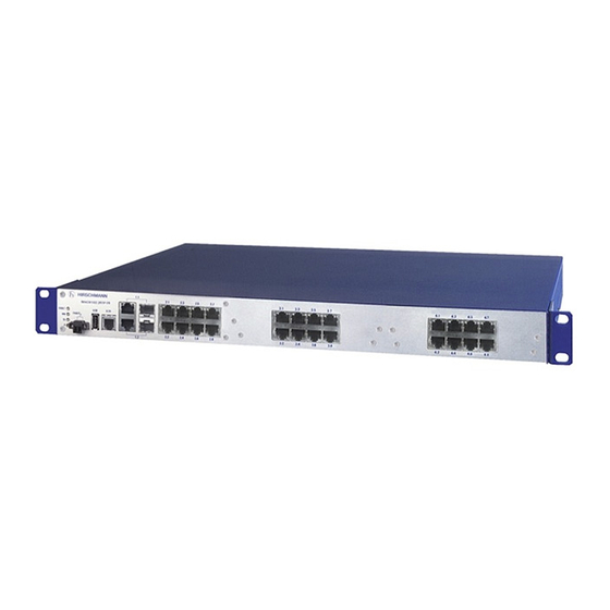
MACH104 Full Gigabit Family
MACH104-20TX-F
FAULT
USB
V.24
FAULT
RM
Sb
P
MACH104-20TX-F...
MACH104-20TX-FR
FAULT
USB
V.24
FAULT
RM
Sb
P
MACH104-20TX-FR...
MACH104-20TX-F-4PoE
FAULT
USB
V.24
FAULT
RM
Sb
P
MACH104-20TX-F-4PoE...
Installation MACH104
Release 08 01/2019
5
7
1
3
2
4
6
8
5
7
1
3
2
4
6
8
P
5
7
1
3
2
4
6
8
9
11
13
15
10
12
14
16
9
11
13
15
10
12
14
16
9
11
13
15
10
12
14
16
https://hirschmann-support.belden.com
17
19
21
23
18
20
22
24
17
19
21
23
18
20
22
24
17
19
21
23
18
20
22
24
Technical support
Advertisement
Table of Contents

Related Manuals for Hirschmann MACH104-20TX-FR Series


Summary of Contents for Hirschmann MACH104-20TX-FR Series
- Page 1 User Manual Installation Industrial Ethernet Workgroup Switch MACH104 Full Gigabit Family MACH104-20TX-F FAULT V.24 FAULT MACH104-20TX-F... MACH104-20TX-FR FAULT V.24 FAULT MACH104-20TX-FR... MACH104-20TX-F-4PoE FAULT V.24 FAULT MACH104-20TX-F-4PoE... Installation MACH104 Technical support Release 08 01/2019 https://hirschmann-support.belden.com...
- Page 2 In addition, we refer to the conditions of use specified in the license contract. You can get the latest version of this manual on the Internet at the Hirschmann product site (www.hirschmann.com). Hirschmann Automation and Control GmbH Stuttgarter Str.
-
Page 3: Table Of Contents
Contents Safety instructions About this manual Legend Description General device description Description of the device variants 1.2.1 MACH104-20TX-F...: Devices with 24 GB ports 1.2.2 MACH104-20TX-FR...: Devices with 24 GB ports and redundant power supply 1.2.3 MACH104-20TX-F-4-PoE...: Devices with 24 GB ports, 4 of them PoE ports Supply voltage 1.3.1 MACH104-20TX-F... - Page 4 Wiring and installing the signal contact Installing the device and grounding 2.4.1 Selecting the assembly location 2.4.2 Mounting on a flat surface 2.4.3 Mounting in a switch cabinet 2.4.4 Mounting on the wall 2.4.5 Grounding the device Operating the device Connecting data cables Making basic settings Default settings...
-
Page 5: Safety Instructions
Operate the device with undamaged components exclusively. The device is free of any service components. In case of a damaged or malfunctioning device, turn off the supply voltage and return the device to Hirschmann for inspection. Qualification requirements for personnel ... - Page 6 The power supply cable is suitable for the voltage, the current and the physical load. Hirschmann recommends a wire diameter of 0.5 mm² to 0.75 mm² (AWG20 up to AWG18). The following requirements apply alternatively: Installation MACH104...
- Page 7 Prerequisites: Relevant when the device is supplied via 1 voltage input: Alternative 1 The power supply complies with the requirements for a limited power source (LPS) as per EN 60950-1. Alternative 2 Relevant for North America: The power supply complies with the requirements according to NEC Class 2. Alternative 3 All of the following requirements are complied with: ...
- Page 8 Supply voltage The supply voltage is connected to the device casing through protective elements exclusively. The supply voltage is electrically isolated from the casing. Device casing Only technicians authorized by the manufacturer are permitted to open the casing. ...
- Page 9 In accordance with the above-named EU directive(s), the EU conformity declaration will be at the disposal of the relevant authorities at the following address: Hirschmann Automation and Control GmbH Stuttgarter Str. 45-51 72654 Neckartenzlingen Germany The product can be used in the industrial sector.
- Page 10 FCC note: This device complies with part 15 of the FCC rules. Operation is subject to the following two conditions: (1) this device may not cause harmful interference; (2) this device must accept any interference received, including interference that may cause undesired operation. Appropriate testing has established that this device fulfills the requirements of a class A digital device in line with part 15 of the FCC regulations.
- Page 11 Installation MACH104 Release 08 01/2019...
- Page 12 Relevant for installations in switch cabinets according to UL 60950-1 Higher ambient air temperature during operation: If installed in a closed switch cabinet or a multi-unit switch cabinet, the ambient air temperature inside the switch cabinet during operation can be higher than the ambient air temperature in the room.
-
Page 13: About This Manual
Command Line Interface reference manual The Network Management Software Industrial HiVision provides you with options for smooth configuration and monitoring. You find further information on the Internet at the Hirschmann product pages: http:// www.hirschmann.com/en/QR/INET-Industrial-HiVision Installation MACH104 Release 08 01/2019... -
Page 14: Legend
Legend The symbols used in this manual have the following meanings: Listing Work step Subheading Installation MACH104 Release 08 01/2019... -
Page 15: Description
The device provides you with a large range of functions, which the manuals for the operating software inform you about. You can download these manuals as PDF files from the Internet on the Hirschmann product pages (www.hirschmann.com). The Hirschmann network components help you ensure continuous communication across all levels of the company. -
Page 16: Description Of The Device Variants
Description of the device variants 1.2.1 MACH104-20TX-F...: Devices with 24 GB ports MACH104-20TX-F... 4 Gigabit Ethernet combo ports 20 Gigabit Ethernet ports 9 11 13 15 17 19 21 23 MACH104-20TX-F FAULT V.24 FAULT 10 12 14 16 18 20 22 24 Figure 1: Overview over interfaces, display and operating elements... -
Page 17: Mach104-20Tx-Fr
1.2.2 MACH104-20TX-FR...: Devices with 24 GB ports and redundant power supply MACH104-20TX-FR... 4 Gigabit Ethernet combo ports 20 Gigabit Ethernet ports The power supply is designed redundantly. 9 11 13 15 17 19 21 23 MACH104-20TX-FR FAULT V.24 FAULT... -
Page 18: Mach104-20Tx-F-4-Poe
1.2.3 MACH104-20TX-F-4-PoE...: Devices with 24 GB ports, 4 of them PoE ports MACH104-20TX-F-4-PoE... 4 Gigabit Ethernet combo ports 20 Gigabit Ethernet ports, 4 of which are PoE-capable Integrated PoE voltage supply for 4 PoE ports 9 11 13 15 17 19 21 23... -
Page 19: Supply Voltage
Supply voltage Note: Note the safety instructions in “Requirements for connecting electrical wires” on page 1.3.1 MACH104-20TX-F... Supply voltage is connected via a non-heating appliance socket. Figure 4: MACH104-20TX-F connections on the back of the device 1 - Power supply 100 V AC ... 240 V AC 2 - MACH104-20TX-F... -
Page 20: Mach104-20Tx-F-4-Poe
1.3.3 MACH104-20TX-F-4-PoE... Supply voltage is connected via a non-heating appliance socket. Figure 6: MACH104-20TX-F-4-PoE... connections on the back of the device 1 - Standard power supply 100 V AC ... 240 V AC 2 - MACH104-20TX-F-4-PoE... device Ethernet ports You can connect end devices and other segments to the device ports using twisted pair cables or optical fibers (F/O). -
Page 21: 100 Mbit/S F/O Port
Figure Function Ports with PoE support: PoE voltage feed BI_DB+ Minus terminal of the supply voltage BI_DB− Minus terminal of the supply voltage BI_DA+ Plus terminal of the supply voltage BI_DD+ BI_DD− BI_DA− Plus terminal of the supply voltage BI_DC+ BI_DC−... -
Page 22: Combo Ports
The PoE ports support the connection and a remote power supply of (for example) IP phones (Voice-over-IP), webcams, sensors, print servers, and WLAN access points. With PoE, these end devices are powered via the twisted pair cable. The following applies to PoE ports: ... -
Page 23: Device State
1.5.1 Device state FAULT These LEDs provide information about conditions which affect the operation of the whole device. The following table applies to the stated device variants only: MACH104-20TX-FR... Display Color Activity Meaning Supply — none Supply voltages 1 and 2 are too low. voltage green lights up... -
Page 24: Port Status
Display Color Activity Meaning ACA memory green Flashing Error in the memory operation operations alternately flashes Saves a configuration file from the storage synchronously medium ACA to the device. 2 × per period flashes Saves a configuration file from the device to synchronously the storage medium ACA. -
Page 25: Management Interfaces
Management interfaces 1.6.1 V.24 interface (external management) The V.24 interface is an RJ11 socket. The V.24 user interface is serial and allows you to connect the following devices directly: External management station (VT100 terminal or PC with appropriate terminal emulation). With this management station, the Command Line Interface (CLI) is available to you. -
Page 26: Usb Interface
In the configuration, you specify how the device uses the signal contact. You find detailed information regarding possible applications and configuration of the signal contact in the software user documentation on the Hirschmann product pages (www.hirschmann.com). Installation MACH104 Release 08 01/2019... -
Page 27: Installation
“Scope of delivery, order numbers and accessories” on page Check the individual parts for transport damage. Installing an SFP transceiver (optional) Prerequisites: Exclusively use Hirschmann SFP transceivers. See “Accessories and order numbers” on page 44. Figure 10: Installing SFP transceivers: Installation sequence Installation MACH104... -
Page 28: Wiring And Installing The Signal Contact
Proceed as follows: Take the SFP transceiver out of the transport packaging (1). Remove the protection cap from the SFP transceiver (2). Push the SFP transceiver with the lock closed into the slot until it latches in (3). Wiring and installing the signal contact FAULT Figure 11: 2-pin terminal block... -
Page 29: Installing The Device And Grounding
Installing the device and grounding The device can be mounted on a flat surface, in a 19" standard switch cabinet, or on the wall. 2.4.1 Selecting the assembly location Select the assembly location according to the safety guidelines (see on page 5 “Safety instructions”). -
Page 30: Mounting On The Wall
Figure 12: Assembly in a switch cabinet with sliding/mounting rails 1 - MACH104 device 2 - sliding/mounting rail 3 - 19" switch cabinet MACH104-20TX-F FAULT V.24 FAULT Figure 13: Mounting the MACH104 in the 19" cabinet Fasten the device by screwing the brackets to the switch cabinet. Note: When operating the device in an environment with strong vibrations, you have the option to additionally fasten the device to the switch cabinet using 2 holding brackets on the back of the device. -
Page 31: Grounding The Device
Additionally attach 2 brackets to the back of the device. See figure 14. You obtain the additional brackets as accessories. See “Accessories and order numbers” on page 44. Fasten the device by screwing the brackets to the wall. Figure 14: Vertical mounting on the wall 2.4.5 Grounding the device... -
Page 32: Operating The Device
Operating the device WARNING ELECTRIC SHOCK Connect only a supply voltage that corresponds to the type plate of your device. Failure to follow these instructions can result in death, serious injury, or equipment damage. Note: Note the safety instructions in “Requirements for connecting electrical wires”... -
Page 33: Making Basic Settings
Input via the V.24 interface Input via the HiView or Industrial HiVision application. You find further information about the applications HiView or Industrial HiVision on the Internet at the Hirschmann product pages: HiView http://www.hirschmann.com/en/QR/INET-HiView Industrial HiVision http://www.hirschmann.com/en/QR/INET-Industrial-HiVision ... -
Page 34: Default Settings
Default settings The device looks for the IP address using DHCP Management password: user, password: public (read only) admin, password: private (read and write) V.24 data rate: 9600 Baud Ring redundancy disabled Ethernet ports: link status is not evaluated (signal contact) ... -
Page 35: Maintenance And Service
Maintenance and service When designing this device, Hirschmann largely avoided using high-wear parts. The parts subject to wear and tear are dimensioned to last longer than the lifetime of the product when it is operated normally. Operate this device according to the specifications. -
Page 36: Deinstallation
Deinstallation Removing the device Disconnect the data cables. Disable the supply voltage. Disconnect the supply voltage. Remove the terminal connector from the device. To detach the device from the switch cabinet or the wall, remove the screws from the brackets on the device. -
Page 37: Technical Data
Technical data General technical data Dimensions See “Dimension drawings” on page 38. Weight MACH104-20TX-F... 9.26 lb (4.2 kg) MACH104-20TX-FR... 9.7 lb (4.4 kg) MACH104-20TX-F-4-PoE... 10.14 lb (4.6 kg) Supply voltage Rated voltage range 100 V AC ... 240 V AC, 50 Hz ... 60 Hz Voltage range including 90 V AC ... -
Page 38: Dimension Drawings
Dimension drawings 462,6 0.13 18.21 0.13 inch 19,3 19,3 0.76 17.48 0.76 EMC and immunity EMC interference immunity IEC/EN 61000-4-2 Electrostatic discharge Contact discharge 6 kV Air discharge 8 kV IEC/EN 61000-4-3 Electromagnetic field 80 MHz ... 3000 MHz max. 20 V/m IEC/EN 61000-4-4 Fast transients (burst) Power line... - Page 39 EMC interference immunity IEC/EN 61000-4-5 Voltage surges Power line, line / line 1 kV Power line, line / ground 2 kV Data line 4 kV IEC/EN 61000-4-6 Conducted disturbances 150 kHz ... 80 MHz 10 V EN 61000-4-9 Pulse magnetic fields 300 A/m EMC interference emission EN 55032...
-
Page 40: Network Range
Network range Note: The line lengths specified for the transceivers apply for the respective fiber data (fiber attenuation and Bandwidth Length Product (BLP)/ Dispersion). 10/100/1000 Mbit/s twisted pair port Length of a twisted pair segment max. 328 ft (100 m) (for Cat5e cable) Table 4: Network range: 10/100/1000 Mbit/s twisted pair port Product code... - Page 41 Product code Mode Wave length Fiber System Example for F/O Fiber /Dispersion M-SFP-... attenuation cable length attenuation -SX/LC... 850 nm 50/125 µm 0 dB ... 7.5 dB 0 mi ... 0.34 mi 3.0 dB/km 400 MHz×km (0 km ... 0.55 km) -SX/LC...
- Page 42 Product code Mode Wave length Wave length Fiber System Example for F/O Fiber Dispersion M-SFP-BIDI... attenuation cable length attenuation Type A LX/LC EEC SM 1310 nm 1550 nm 9/125 µm 0 dB ... 11 dB 0 km ... 12.43 mi 0.4 dB/km 3.5 ps/(nm×km) (0 km ...
-
Page 43: Power Consumption/Power Output
Power consumption/power output MACH104device Maximum Maximum power consumption power output MACH104-20TX-F... 35 W 119 Btu (IT)/h MACH104-20TX-FR... 35 W 119 Btu (IT)/h MACH104-20TX-F-4-PoE..., with 4 × 110 W 170 Btu (IT)/h Class 0 Powered-Device connected Installation MACH104 Release 08 01/2019... -
Page 44: Scope Of Delivery, Order Numbers And Accessories
Scope of delivery, order numbers and accessories MACH104-20TX-F... Number Article 1 × General safety instructions 1 × Device 1 × 2-pin terminal block for signal contact 2 × Brackets with fastening screws (pre-mounted) 1 × Casing feet, stick on 1 ×... - Page 45 943 042-001 M-SFP-LH/LC EEC 943 898-001 M-SFP-LH+/LC 943 049-001 M-SFP-LH+/LC EEC 942 119-001 SFP-GIG-LX/LC 942 196-001 SFP-GIG-LX/LC EEC 942 196-002 a. You find further information on certifications on the Internet at the Hirschmann product pages (www.hirschmann.com). Installation MACH104 Release 08 01/2019...
- Page 46 SFP-FAST-MM/LC EEC 942 194-002 SFP-FAST-SM/LC 942 195-001 SFP-FAST-SM/LC EEC 942 195-002 a. You find further information on certifications on the Internet at the Hirschmann product pages (www.hirschmann.com). Bidirectional Gigabit Ethernet SFP transceiver Order number M-SFP-BIDI Type A LX/LC EEC 943 974-001...
-
Page 47: Underlying Technical Standards
If your device has a shipping approval according to Germanischer Lloyd or DNV GL, you find the respective approval mark printed on the device label. You will find out whether your device has other shipping approvals on the Hirschmann website under www.hirschmann.com in the product information. -
Page 48: A Further Support
Further support Technical questions For technical questions, please contact any Hirschmann dealer in your area or Hirschmann directly. You find the addresses of our partners on the Internet at http:// www.hirschmann.com. A list of local telephone numbers and email addresses for technical support... - Page 49 Installation MACH104 Release 08 01/2019...
Need help?
Do you have a question about the MACH104-20TX-FR Series and is the answer not in the manual?
Questions and answers