Table of Contents
Advertisement
User Manual
Installation
Industrial ETHERNET Ruggedized Switch
MACH 1000 Family
USB
V.24
LS
3
P
RM
StandBy
R1 R2
FAULT
MACH 1020
5
MACH 1020
USB
V.24
LS
1
3
RM
StandBy
P
2
R1 R2
FAULT
MACH 1030
5
MACH 1030
USB
USB
V.24
V.24
1
3
P
P
RM
RM
StandBy
StandBy
2
R1 R2
R1 R2
FAULT
FAULT
MACH 1000
5
MACH 1032
V.24
V.24
USB
USB
LS
1
1
3
3
P
P
RM
RM
StandBy
StandBy
LS
2
2
R1 R2
R1 R2
FAULT
FAULT
MACH 1000
5
5
MACH 1132
MACH 1000
Release 02 10/10
DA
LS
DA
7
8
4
6
9
10
DA
LS
DA
4
7
8
6
10
9
8
4
7
6
9
10
DA
LS
DA
4
4
7
8
DA
6
6
9
10
11
12
15
16
LS
DA
LS
DA
13
14
17
18
11
12
15
16
LS
DA
LS
DA
13
14
17
18
11
12
15
16
LS
DA
LS
DA
14
13
17
18
11
12
15
16
LS
DA
LS
DA
13
14
17
18
RM
StandBy
P
1
3
5
7
9 11 13 15 17 19 21 23
R1 R2
FAULT
2
4
6
8 10 12 14 16 18 20 22 24
ETHERNET Service Port
LS
DA
LS
DA
23
24
19
20
21
22
25
26
LS
DA
LS
DA
24
19
20
23
25
26
21
22
24
19
20
23
25
26
21
22
22
19
20
23
24
26
21
22
25
Technical Support
HAC.Support@Belden.com
Advertisement
Table of Contents

Subscribe to Our Youtube Channel
Related Manuals for Hirschmann MACH 1020


Summary of Contents for Hirschmann MACH 1020
-
Page 1: User Manual
User Manual Installation Industrial ETHERNET Ruggedized Switch MACH 1000 Family V.24 StandBy R1 R2 FAULT MACH 1020 MACH 1020 V.24 StandBy R1 R2 FAULT MACH 1030 MACH 1030 V.24 V.24 StandBy StandBy R1 R2 R1 R2 FAULT FAULT MACH 1000 MACH 1032 V.24... - Page 2 In addition, we refer to the conditions of use specified in the license contract. You can get the latest version of this manual on the Internet at the Hirschmann product site (www.beldensolutions.com). Printed in Germany Hirschmann Automation and Control GmbH Stuttgarter Str.
-
Page 3: Table Of Contents
Contents Safety instructions About this Manual Legend Device description Description of the device variants Combination options Assembly and start-up Installing the device 2.1.1 Unpacking and checking 2.1.2 Installing the SFP modules (optional) 2.1.3 Connecting the power unit connections for supply voltage and signal contact 2.1.4 Installing the device and grounding 2.1.5 Startup procedure 2.1.6 Connecting the data lines... -
Page 4: Safety Instructions
Safety instructions This documentation contains instructions which must be observed to ensure your own personal safety and to avoid damage to devices and machinery. Certified usage The device may only be employed for the purposes described in the catalog and technical description, and only in conjunction with external devices and components recommended or ... - Page 5 Warning: – If the neutral conductor or the negative terminal of the supply voltage is not grounded – If you are using a DC voltage greater than 125 VDC for the supply voltage install a suitable input fuse. For power supply units with product code “G” or “M”, use a slow- blow fuse with a nominal rating of 2.5 A for the voltage supply input.
- Page 6 Warning! Never insert sharp objects (small screwdrivers, wires, etc.) into the inside of the product. There is the risk of an electric shock. The device must be installed in the horizontal or upright position, either in the switch cabinet or on the wall (see on page 30 “Installing the device and grounding”) The device is not intended for operation as a...
-
Page 7: General Safety Instructions
trained or directed or authorized to switch on and off, to ground and to label power circuits and devices or systems in accordance with current safety engineering standards; trained or directed in the care and use of appropriate safety equipment in accordance with the current standards of safety engineering;... - Page 8 In accordance with the above-named EU directive(s), the EU conformity declaration will be at the disposal of the relevant authorities at the following address: Hirschmann Automation and Control GmbH Stuttgarter Str. 45-51 72654 Neckartenzlingen Tel.: +49 1805 141538 The product can be used in the industrial sector.
- Page 9 Warning! This is a class A device. This device can cause interference in living areas, and in this case the operator may be required to take appropriate measures. Warning! The assembly guidelines provided in these instructions must be strictly adhered to in order to observe the EMC threshold values. FCC note: ...
-
Page 10: About This Manual
About this Manual The “Installation” user manual contains a device description, safety instructions, a description of the display, and the other information that you need to install the device. The following manuals are available as PDF files on the CD-ROM supplied: ... -
Page 11: Device Description
Device description The Ruggedized Switch for Substations and Transportation MACH 1000 Family provides you with a wide range of Switch variants. You set up your own Switch according to your requirements regarding the number of ports, transmission speed, media type, connector type, temperature range, voltage range and software variant. -
Page 12: Description Of The Device Variants
SNMP 802.1x port authentication Real Time Clock (Professional software variant) The addition, to the MACH 1000 Ruggedized Switch series, of the switches of the Open Rail range, the MICE range, the backbone switches of the MACH 3000 and MACH 4000 ranges, the BAT wireless transmission system, the EAGLE security system, and products for the LION control room, provides continuous communication across all levels of the company. - Page 13 - twisted pair RJ45 sockets (2 x 2 sockets) or - 2 x SFP slots plus 2 x twisted pair RJ45 sockets. The MAR1130-... and MAR1132-... devices have an additional Fast Ethernet port on the front of the device that you can use for diagnosis purposes.
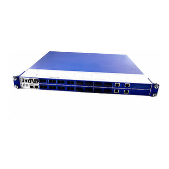
- Page 14 Front view of the MACH 1000 with 2 Gigabit ports MACH 1000 V.24 StandBy R1 R2 FAULT MACH 1000 Figure 1: 1 - LED display elements 2 - USB interface 3 - V.24 connection for external management ...
- Page 15 Gigabit ETHERNET Fast ETHERNET GE ports 1 to 4 FE ports 1 to 24, free choice of connections Module position empty 1000 Mbit/s 2 * twisted pair TX, RJ45, 10/100 Mbit/s Fiber optic, SFP slots 2 * Multimode FX DSC 100 Mbit/s 2 * Multimode FX MTRJ 100 Mbit/s 2 * Multimode FX ST 100 Mbit/s 2 * Singlemode FX DSC 100 Mbit/s...
- Page 16 Front view of the MACH 1000 with PoE MACH 1000 V.24 V.24 StandBy StandBy R1 R2 R1 R2 FAULT FAULT MACH 1000 Figure 4: 1 - LED display elements 2 - USB interface 3 - V.24 connection for external management ...
- Page 17 Views of the MACH 1000, ports in the back MACH 1000 StandBy 9 11 13 15 17 19 21 23 R1 R2 FAULT 6 8 10 12 14 16 18 20 22 24 ETHERNET Service Port Figure 5: Front panel: ...
-
Page 18: Combination Options
Combination options The product designation of your device is made from combining the desired product characteristics in accordance with the following table. The corresponding short designation is in column 3. Item Characteristic Ident. Property 1 to 7 Product MAR1020 MACH Ruggedized Fast Ethernet Switch MAR1030 MACH Ruggedized Gigabit Ethernet Switch MAR1022... - Page 19 Item Characteristic Ident. Property 23 to 24 10/100 Mbit/s ports 13 + 14 See 11 to 12 25 to 26 10/100 Mbit/s ports 15 + 16 See 11 to 12 27 to 28 10/100 Mbit/s ports 17 + 18 See 11 to 12 29 to 30 10/100 Mbit/s ports 19 + 20 See 11 to 12 31 to 32 10/100 Mbit/s ports 21 + 22...
- Page 20 Example of MACH 1000 product designation MACH Ruggedized Switch with Gigabit ports 2 * combo port (SFP slot: 100/1000 Mbit/s, alternatively twisted pair RJ45 socket: 10/100/ 1000 Mbit/s) 10/100 Mbit/s ports 1 + 2: 2 * twisted pair TX, RJ45, 10/100 Mbit/s 10/100 Mbit/s ports 3 + 4: 2 * Multimode FX DSC 100 Mbit/s 10/100 Mbit/s ports 5 + 6:...
-
Page 21: Assembly And Start-Up
Before attaching an SFP module, first remove the protective cap over the socket. Push the SFP module with the lock closed into the socket until it latches audibly in place. Note: Only use Hirschmann SFP modules (see page 50 “Accessories”). MACH 1000... -
Page 22: Connecting The Power Unit Connections For Supply Voltage And Signal Contact
2.1.3 Connecting the power unit connections for supply voltage and signal contact Connect the power supply and signal lines. Note: Note the safety instructions (see on page 4 “Supply voltage”) and only connect a supply voltage that corresponds to the type plate of your device. - Page 23 V.24 V.24 StandBy StandBy -/N +/L R1 R2 R1 R2 FAULT FAULT MACH 1000 Relay 2 -/N +/L Relay 2 -/N +/L Figure 9: MACH 1000 device variants (back of device), plugged voltage connection 1 - Power unit 1 ...
- Page 24 Note: For device variants without PoE: For device variants with two power units, if there is non-redundant voltage supply, the device reports the failure of one supply voltage. You can prevent this message by applying the supply voltage via both inputs, or by changing the configuration in the Management.
- Page 25 Note: Observe the permitted voltage ranges for devices with type „T“ certifications (EN 50155 Railway (train), see product code item 38 in table Power supply type G and M: nominal voltage 110 VDC Power supply type C and L: nominal voltage 36 VDC ...
- Page 26 Relay Figure 11: Back of MACH 1000 device with power unit “C”, DC voltage (18...60 VDC) Connecting 1 - Supply voltage 2 - Signal contact Relay -/N +/L Relay -/N +/L Figure 12: Back of MACH 1000 device with power unit “G”, ...
- Page 27 Connection Type “C” Type “G” VDC Type “G” VAC , pin 1 Protective conductor Protective conductor Protective conductor -/N, pin 2 Minus terminal of the Minus terminal of the Neutral conductor supply voltage supply voltage +/L, pin 3 Plus terminal of the Plus terminal of the “Phase”...
- Page 28 Note: Note the safety instructions (see on page 4 “Supply voltage”) and only connect a supply voltage that corresponds to the type plate of your device. Make sure that the contact load capability of the signal contact is not exceeded (see on page 44 “Technical data”).
- Page 29 Relay Relay -/N +/L -/N +/L Figure 15: Back of MACH 1000 device with power unit “M”, AC voltage 90-265 VAC (right image) or DC voltage 77-300 VDC (left image) Connecting 1 - Supply voltage ...
-
Page 30: Installing The Device And Grounding
The signal contact monitors proper functioning of the device, thus enabling remote diagnostics. You can specify the type of function monitoring in the Management. Pin assignment: for MACH 1000 devices – with terminal voltage supply (see fig. 11), (see fig. 12) –... - Page 31 Warning! If the device is installed in a 19" switch cabinet without sliding/ mounting rails, increased vibration can cause damage to the device and/or its modules. For more information on sliding/mounting rails and how to install them, please contact your switch cabinet manufacturer. ...
- Page 32 Figure 17: Vertical mounting on the wall MACH 1000 Release 02 10/10...
- Page 33 482,6 44,2 465,9 482,6 465,9 Figure 18: MACH 1000, dimensions of device variants MACH 1000 Release 02 10/10...
-
Page 34: Grounding The Device
Grounding the device The device is grounded as follows: for MACH 1000 devices with terminal connection voltage supply via a separate spring-loaded terminal. This is located at the 1 or 2 power supply modules on the back of the device, at pin 1 (see fig. - Page 35 n.c. n.c. n.c. Figure 19: Pin assignment of a TP/TX interface in MDI-X mode, RJ45 socket Note: In substation applications, the RJ45 ports are used to connect to additional communication devices such as routers or telecommunication multiplexers that are installed in close proximity to the device (i.e. less than 3 meters away).
- Page 36 Keep the length of the data cables as short as possible - ideally max. 3m long. You should not use any copper data cables for the data transmission between buildings. Power supply and data cables should not run parallel over longer distances, and ideally they should be installed in separate cable channels.
- Page 37 Connect the cable shield to the connector housing. The patch cables for operating the device are shown in the following figure: (10) Figure 22: Patch cables for operating the device (1) - Connection cables M12-4 on M12-4, crossed ...
-
Page 38: Display Elements
10 Mbit/s F/O connection 10 MBit/s F/O ports (ST connectors) enable the connection of terminal devices or independent network segments in compliance with the IEEE 802.3 10BASE-FL standard. Full or half duplex mode State on delivery: full duplex FDX 100 Mbit/s F/O connection ... - Page 39 V.24 StandBy R1 R2 FAULT MACH 1000 Figure 23: Display elements of MACH 1000, device variants with ports on the front 1 - Device status display elements 2 - Port status display elements StandBy 9 11 13 15 17 19 21 23 8 10 12 14 16 18 20 22 24 R1 R2 FAULT...
-
Page 40: Port State
RM and Stand-by - display saving processes of the AutoConfiguration Adapter (ACA) Flashing alternately Error during saving process. LEDs flash synchronously, two Loading configuration from the ACA. times a second LEDs flash synchronously, Saving the configuration in the ACA. once a second Applies to software releases previous to 06.0.00: Display Color Activity... -
Page 41: Default Settings
LS - data, link status (one green/yellow LED or one green and one yellow LED) Not glowing No valid connection. Glowing green Valid connection. Flashing green (1 time a period) Port is switched to stand-by. Flashing green (3 times a Port is switched off. - Page 42 Figure Function VCC (VBus) - Data + Data Ground (GND) Table 8: Pin assignment of the USB interface V.24 interface (external management) The V.24 interface is an RJ11 socket. The V.24 interface is a serial interface which allows you to connect the following devices locally: ...
-
Page 43: Disassembling The Device
Disassembling the device To detach the device from the switch cabinet or the wall, remove the screws from the brackets on the device. V.24 StandBy R1 R2 FAULT MACH 1000 MACH 1000 MACH 1000 Release 02 10/10... -
Page 44: Technical Data
Technical data General technical data Dimensions 448 × 310 × 44 mm MAR10... W × D × H (without brackets) 448 × 345 × 44 mm MAR11... (deeper chassis structure) (without brackets) Weight (incl. MAR1020-... fully equipped max. - Page 45 77 V … 300 V Power supply for Input voltage DC device variants (110 V … 250 V -30% … +25%) 90 V … 265 V with PoE Input voltage AC (110 V … 230 V -20% … +15%) Output voltage 48 V DC ±...
- Page 46 EMC interference Description Test level immunity IEC/EN 61850- 3:2002 EMI TYPE tests, test in comp. with IEC/EN 61000-4-5 Voltage surges DC power line +/- 2 kV line / earth; +/- 1 kV line / line AC power line +/- 4 kV line / earth; +/- 2 kV line / line Data line +/- 4 kV line / earth IEC/EN 61000-4-6...
- Page 47 EMC emitted interference EN 55022 Class A FCC 47 CFR Part Class A German Lloyd Classification + Construction Guidelines VI-7-3 Part 1 Ed.2001 Environment type Description Test level tests, test in comp. with IEC 60068-2-1 Cold -40 °C, 16 hours IEC 60068-2-2 Dry heat +85 °C, 16 hours...
- Page 48 Product Wave Fiber System Expansion Fiber data code length attenuatio M-FAST- SFP-... -MM/LC... MM 1310 nm 50/125 µm 0-8 dB 0-5 km 1.0 dB/km, 800 MHz*km -MM/LC... MM 1310 nm 62.5/125 µm 0-11 dB 0-4 km 1.0 dB/km, 500 MHz*km -SM/LC...
-
Page 49: Scope Of Delivery
MM = Multimode, SM = Singlemode, LH = Singlemode Longhaul Power consumption/power output Name Power Power output consumpti Basic devices MAR1020-... basic device (without Fast Ethernet modules) 7.5 W 25.6 Btu (IT)/h MAR1030-... basic device (incl. 2 Gigabit Ethernet module 10.5 W 35.9 Btu (IT)/h combo ports, without Fast Ethernet modules) - Page 50 Order numbers/product description Combination options and device names (see table Accessories Note: Please note that products recommended as accessories may have characteristics that do not fully correspond to those of the corresponding product. This may limit their possible usage in the overall system. Name Operating Order number...
- Page 51 Name Operating Order number temperature (chassis) M-SFP-BIDI Type B LH/LC EEC -40 °C to +70 °C 943 975-002 M-SFP-BIDI Bundle LX/LC EEC (Type A + B) -40 °C to +70 °C 943 974-101 M-SFP-BIDI Bundle LH/LC EEC (Type A + B) -40 °C to +70 °C 943 975-101 Underlying norms and standards...
- Page 52 MACH 1000 Release 02 10/10...
-
Page 53: A Further Support
Further Support Technical Questions and Training Courses In the event of technical queries, please contact your local Hirschmann distributor or Hirschmann office. You can find the addresses of our distributors on the Internet: www.beldensolutions.com. Our support line is also at your disposal: ...
Need help?
Do you have a question about the MACH 1020 and is the answer not in the manual?
Questions and answers