Table of Contents
Advertisement
Quick Links
Download this manual
See also:
Setup Manual
Advertisement
Table of Contents

Related Manuals for Extron electronics DVC 501 SD


Summary of Contents for Extron electronics DVC 501 SD
- Page 1 User Guide Signal Processors DVC 501 SD SDI Converter 68-1518-01 Rev. A 07 11...
- Page 2 Safety Instructions • English Warning Power sources • This equipment should be operated only from the power source indicated on the product. This This symbol is intended to alert the user of important operating and equipment is intended to be used with a main power system with a grounded (neutral) conductor. The third maintenance (servicing) instructions in the literature provided with the (grounding) pin is a safety feature;...
- Page 3 FCC Class A Notice This equipment has been tested and found to comply with the limits for a Class A digital device, pursuant to part 15 of the FCC Rules. Operation is subject to the following two conditions: This device may not cause harmful interference. This device must accept any interference received, including interference that may cause undesired operation.
- Page 4 Conventions Used in this Guide In this user guide, the following conventions are used: NOTE: A note draws attention to important information. TIP: A tip provides a suggestion to make working with the device easier. CAUTION: A caution indicates a potential hazard to equipment or data. WARNING: A warning warns of things or actions that might cause injury, death, or other severe consequences.
-
Page 5: Table Of Contents
Connecting to the USB Config Port ....6 Included Parts ..........29 Optional Accessories ........29 Operation ..............9 Mounting the DVC 501 SD Converter ....29 Front Panel ............9 Rack Mounting ..........29 Powering On............. 10 Under-desk Mounting ........30 Default Cycle .......... - Page 6 DVC 501 SD • Contents...
-
Page 7: Introduction
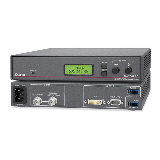
DVC 501 SD converter. About the DVC 501 SD Converter The Extron DVC 501 SD is a digital video converter that receives SDI, HD-SDI, and 3G-SDI serial digital video signals and converts them to DVI-D and analog RGB or component video. -
Page 8: Application Diagram
Rack and furniture mountable 1U, half rack width metal enclosure • Internal universal power supply — The 100-240 VAC, 50-60 Hz, international power supply provides worldwide power compatibility. Application Diagram The following diagram shows an example of a DVC 501 SD application. Extron SI 28 Surface-mount Speakers... -
Page 9: Installation
Installation This section gives an overview of the steps for installing the DVC 501 SD. It also provides a description of the rear panel connectors and instructions for cabling. Topics include: Installation Overview • • Rear Panel • Connecting for Remote Control Installation Overview CAUTION: Installation and service must be performed by authorized personnel only. -
Page 10: Rear Panel
Rear Panel The illustration below shows the connectors on the DVC 501 SD rear panel. CAUTION: Use electrostatic discharge precautions (be electrically grounded) when making connections. Electrostatic discharge (ESD) can damage equipment, although you may not feel, see, or hear it. -
Page 11: Connecting For Remote Control
Connect the ground wire to the last pin, which plugs into the ground port, marked with _. Plug the cable into the RS-232 portion of the 5-pole captive screw connector on the DVC rear panel. See the illustration on the next page. DVC 501 SD • Installation... -
Page 12: Connecting To The Usb Config Port
Use a USB A-to-mini-B cable to connect the DVC USB Config port to a USB port on your computer. Mini Type B Type A USB 1 Ports USB Cable MENU ADJUST NEXT CONFIG Extron Computer DVC SERIES DIGITAL VIDEO CONVERTER Converter Front Panel Figure 6. Connecting to the Config Port DVC 501 SD • Installation... - Page 13 If this is the first time you have connected a DVC 501 SD to this particular USB port on your computer, the Found New Hardware Wizard opens. On the first screen, specify whether you want the computer to connect to Windows Update in order to search the ®...
- Page 14 Figure 8. Selecting the Radio Button to Install the USB Driver Automatically Your computer locates the driver needed for it to communicate with the DVC 501 SD via the USB port. When the Completed screen appears, click to close the wizard.
-
Page 15: Operation
Operation This section discusses the functions available through the front panel to set up and operate the DVC 501 SD. Topics include: Front Panel • • Powering On Menus on the LCD Screen • • Resetting • Front Panel Lockout (Executive Mode) Updating Firmware •... -
Page 16: Powering On
The default cycle changes when any of the following conditions exist: No input connected — A single screen is displayed, indicating that there is no input • signal. INPUT NO SIGNAL! Figure 11. Default Screen When No Input Is Connected DVC 501 SD • Operation... -
Page 17: Menus On The Lcd Screen
Configuration and Control” section. Menus on the LCD Screen The DVC 501 SD menus that are displayed on the LCD screen enable you to configure and operate the converter. The menu navigation buttons (Menu and Next) are located to the right of the LCD screen. Press these buttons to cycle through the available menus and submenus, and use the horizontal and vertical Adjust knobs to select options. - Page 18 Menu button. Default Cycle Menu OUTPUT CONFIG 30 sec. Menu AUDIO CONFIG 30 sec. Menu ADVANCED CONFIG 30 sec. Menu EXIT MENU Menu PRESS NEXT 30 sec. Next Figure 14. Main Menu Flow Diagram DVC 501 SD • Operation...
-
Page 19: Output Configuration Menu
(default). Resolutions and refresh rates The output resolution and refresh rate follow those of the source device. The table below shows the resolutions and refresh rates on the DVC 501 SD. Resolution/ 23.98 Hz 24 Hz 25 Hz 29.97 Hz 30 Hz 50 Hz 59.94 Hz 60 Hz... -
Page 20: Audio Config Menu
5-pole captive screw audio connector. Rotate either Adjust knob until the desired channel pair number ( through ) is displayed within the angle brackets. DECODE AUDIO ON PAIR <1> Figure 17. Example of a Decode Audio on Pair <N> LCD Submenu DVC 501 SD • Operation... -
Page 21: Advanced Config Menu
The illustration on the next page shows the test patterns that are available on the DVC. NOTE: Test patterns are available only if an input device is connected to the Input connector and a valid input signal is present. DVC 501 SD • Operation... -
Page 22: Exiting The Menu System
Alternatively, wait until the menu system times out and the default cycle resumes (approximately 30 seconds). Resetting You can perform the following types of reset on the DVC 501 SD: • Firmware and settings: To reset the DVC to its factory-installed firmware version, press the front panel Menu button while connecting power to the unit. -
Page 23: Front Panel Lockout (Executive Mode)
Front Panel Lockout (Executive Mode) To prevent accidental changes to settings, you can lock the DVC 501 SD front panel controls by placing the converter in lock (executive) mode. While the DVC is in lock mode, RS-232 communication remains available, as well as the ability to exit lock mode. - Page 24 Open Window for the Firmware Loader CAUTION: Valid firmware files must have the file extension .s19. A file with any other extension is not a firmware upgrade for this product and could cause the DVC to stop functioning. DVC 501 SD • Operation...
- Page 25 On the Add Device window, the path to the new firmware file is displayed in the Path field. Click . The Add Device window closes, and the DVC 501 SD name and information appear in the Devices section. Figure 22. Firmware Loader Window with a DVC 501 SD Device Added...
- Page 26 Status column. Figure 24. Firmware Upload Complete The LCD screen briefly displays the Extron S logo, then returns to the default cycle. When the firmware upload and unit reset are complete, close the Firmware Loader window. DVC 501 SD • Operation...
-
Page 27: Remote Configuration And Control
Command and Response Table Communication Ports The DVC 501 SD can be remotely controlled via a host computer or other device (such as a control system) that is connected to the rear panel RS-232 port or the front panel USB Config port. -
Page 28: Error Responses
Command and Response Table for SIS commands, later in this section, lists the commands that the DVC 501 SD converter recognizes as valid, the responses that are returned to the host, a description of the command function or the results of executing the command, and command examples. -
Page 29: Symbol Definitions
1 = RGBS 2 = RGsB 3 = YUV bi-level 4 = YUV tri-level X& 1 through 8 SDI audio channels (AES stereo pairs) 0 through -18 dB (-5dB = 5) Audio attenuation level DVC 501 SD • Remote Configuration and Control... -
Page 30: Command And Response Table
Increment attenuation Increase the attenuation level by +1 dB. Decrement attenuation – g X* ] Decrease the attenuation level by –1 dB. View attenuation X* ] View the current audio attenuation level. DVC 501 SD • Remote Configuration and Control... -
Page 31: Advanced Configuration
Query firmware build n.nn.nnnn View the firmware version and build number. Query part number 60-1033-01 View the unit part number. X# ] View internal temp. 20STAT View internal temperature in degrees Celsius. DVC 501 SD • Remote Configuration and Control... -
Page 32: Reference Information
Reference Information This section provides reference information on the DVC 501 SD. The following topics are covered: Specifications • • Part Numbers and Accessories • Mounting the DVC 501 SD Converter Specifications Video Signal type ........SDI, HD-SDI, and 3G-SDI digital video signals Data rates ........ -
Page 33: Video Output
Serial control pin configuration ..3 = Tx, 4 = Rx, 5 = GND USB control ports ......1 front panel female mini USB type B USB standards ........ USB 2.0, low speed Program control ......Extron Simple Instruction Set (SIS) DVC 501 SD • Reference Information... - Page 34 EMI/EMC ......... CE, C-tick, FCC Class A, ICES, VCCI MTBF ..........30,000 hours Warranty ........3 years parts and labor NOTES: • All nominal levels are at ±10%. • Specifications are subject to change without notice. DVC 501 SD • Reference Information...
-
Page 35: Part Numbers And Accessories
UC50' Universal Projector Control cable, 50' (15.2 m) 26-518-01 UC100' Universal Projector Control cable, 100' (30.4 m) 26-518-02 Mounting the DVC 501 SD Converter Rack Mounting UL guidelines for rack mounting The following Underwriters Laboratories (UL) guidelines pertain to the installation of the DVC 501 SD in a rack: •... -
Page 36: Under-Desk Mounting
Under-desk Mounting The DVC 501 SD can also be mounted under furniture, such as a table or podium surface, using the optional MBU 125 under-desk mounting kit (see “Optional Accessories”... -
Page 37: Through-Desk Mounting
Figure 28. Through-desk Mounting the DVC 501 SD Hold the DVC against the inside of the surface through which it will be mounted. On the inside of the mounting surface, mark the four screw holes and the material to be removed (approximately 1.2 inches by 6.9 inches [3.0 cm by 17.5 cm]). - Page 38 Extron Warranty ® Extron Electronics warrants this product against defects in materials and workmanship for a period of three years from the date of purchase. In the event of malfunction during the warranty period attributable directly to faulty workmanship and/or materials, Extron Electronics will, at its option, repair or replace said products or components, to whatever extent it shall deem necessary to restore said product to proper operating condition, provided that it is returned within the warranty period, with proof of purchase and description of malfunction to: USA, Canada, South America,...
Need help?
Do you have a question about the DVC 501 SD and is the answer not in the manual?
Questions and answers