Table of Contents
Advertisement
Quick Links
Advertisement
Table of Contents

Subscribe to Our Youtube Channel
Related Manuals for Extron electronics DVC 501 SD


Summary of Contents for Extron electronics DVC 501 SD
- Page 1 User Guide Signal Processors DVC 501 SD SDI Converter 68-1518-01 Rev. A 07 11...
- Page 2 Warning This equipment should be operated only from the power source indicated on the product. This This symbol is intended to alert the user of important operating and equipment is intended to be used with a main power system with a grounded (neutral) conductor. The third maintenance (servicing) instructions in the literature provided with the (grounding) pin is a safety feature;...
- Page 3 FCC Class A Notice This equipment has been tested and found to comply with the limits for a Class A digital device, pursuant to part 15 of the FCC Rules. Operation is subject to the following two conditions: This device may not cause harmful interference. This device must accept any interference received, including interference that may cause undesired operation.
- Page 4 Conventions Used in this Guide In this user guide, the following conventions are used: NOTE: A note draws attention to important information. TIP: A tip provides a suggestion to make working with the device easier. CAUTION: A caution indicates a potential hazard to equipment or data. WARNING: A warning warns of things or actions that might cause injury, death, or other severe consequences.
-
Page 5: Table Of Contents
Contents Remote Configuration and Control Introduction ....21 ............1 Communication Ports ........21 ..........1 ........21 ....... 1 ........ 21 Features .............. 1 ..........22 Application Diagram ........... 2 ..22 Symbol Definitions ........23 Installation .............. 3 Command and Response Table ...... -
Page 7: Introduction
Introduction include: About this Guide About the DVC 501 SD Converter Features Application Diagram About this Guide This guide provides information for experienced installers on how to install, configure, and About the DVC 501 SD Converter the unit is set for component video output. -
Page 8: Application Diagram
I- D 0 .5 0 - 2 HD Projector Extron /6 0 DVC 501 SD SDI/HD-SDI to DVI and RGBHV RGB/YUV Converter HD-SDI HD-SDI Flat Panel Display Video Capture HDTV Camera Figure 1. Connection Diagram for a DVC 501 SD... -
Page 9: Installation
Disconnect power from the converter and ensure that all other devices that will be connected to it are powered off. (Optional) Mount the unit in a rack or to furniture (see “Mounting the DVC 501 SD Converter” in the “Reference Information” section). Connect the input. in figure 2 on the next page). -
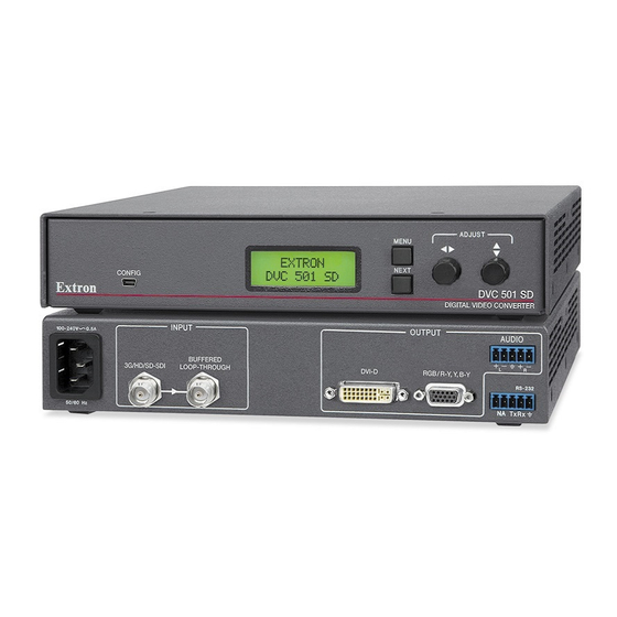
Page 10: Rear Panel
3G/HD/SD-SDI LOOP-THROUGH RGB/R-Y,Y,B-Y RS-232 50/60 Hz Tx Rx Figure 2. DVC 501 SD Rear Panel AC power connector 3G/HD/SD-SDI connector Buffered loop-through DVI-D output connector on this buffered output. The following table shows the pin assignments for this connector. Signal... -
Page 11: Connecting For Remote Control
Audio output connector — Connect an audio device to this female 5-pole 3.5 mm connector as shown below. Ring Sleeves Sleeves Do not tin the wires! Ring Balanced Audio Output Unbalanced Audio Output Figure 4. Audio Output Connector Wiring CAUTIONS: The length of the exposed wires in the stripping process is critical. - Page 12 RS-232 DVC 501 SD or Rear Panel RS-232 Port Tx Rx 1 2 3 NOTE: Connect a ground wire between the DVC and the computer or control system. Ground ( ) Receive (Rx) Transmit (Tx) Transmit (Tx) Receive (Rx) NOTE: If you use cable that has a drain...
- Page 13 ® Figure 7. Found New Hardware Wizard Opening Screen Select the radio button if you want your computer to Yes, this time only Select if you want the computer to Yes, now and every time I connect a device Select No, not this time...
- Page 14 Click . On the next screen, make sure that the Next Install the software radio button is selected, then click (you do not automatically (Recommended) Next need to insert a disc). Figure 8. Selecting the Radio Button to Install the USB Driver Automatically Finish to close the wizard.
-
Page 15: Operation
CONFIG DVC 501 SD DIGITAL VIDEO CONVERTER Figure 9. DVC 501 SD Front Panel The front panel features and controls shown in the illustration above are described starting below. Config port LCD screen — Displays menus, messages, and your selections from menus and “Menus on the LCD... -
Page 16: Powering On
10 seconds, is displayed. The unit part number and current firmware EXTRON DVC 501 SD version are displayed after approximately another 5 seconds. After those screens, the default cycle begins, in which the LCD screen alternates every 5 seconds between the input signal type and data rate, and the output resolution and refresh rate. -
Page 17: Menus On The Lcd Screen
Overheating — The screen is added to the default cycle if Temperature Overload!!! the internal temperature of the unit exceeds 65 °C (149 °F). INPUT INPUT TEMPERATURE HDSDI 1.485G OVERLOAD!!! 720p @59.94Hz 5 sec. 5 sec. 5 sec. Figure 12. Example of the Default Cycle When the Unit Is Overheating Video muted —... - Page 18 NOTE: The menus time out and the default cycle is displayed after 30 seconds of inactivity; however, any selections you made with the Adjust knobs are saved and remain in effect until you change them or reset the unit to factory defaults (see “Resetting,”...
-
Page 19: Output Configuration Menu
Output Configuration Menu The output configuration menu allows you to set the output resolution and refresh rate, the the output configuration submenus and the adjustments that can be made from them. Default Cycle Menu *This screen appears only if RGBHV is selected for the format. OUTPUT FORMAT SYNC... -
Page 20: Audio Config Menu
Audio Config Menu The Audio Config menu enables you to adjust the level of attenuation, mute and unmute the audio, and select the pair of audio channels on which to extract the audio from the 3G-SDI, HD-SDI, or SD-SDI signal. The flow diagram below shows the audio configuration submenus and the adjustments that can be made from them. -
Page 21: Advanced Config Menu
Advanced Config Menu The Advanced Config menu enables you to select a test pattern and to view the internal temperature of the unit. The flow diagram below shows the advanced configuration menu and submenus and the adjustments that can be made from them. AUDIO CONFIG Menu... -
Page 22: Resetting
1.78 Aspect 1.85 Aspect Alt Pixels 2.35 Aspect Figure 19. DVC 501 SD Test Patterns Int. Temp. screen Fahrenheit and Celsius. This is an information-only screen; no adjustments can be made from it. Exiting the Menu System To exit the menu system, press the Menu button repeatedly until the EXIT MENU PRESS NEXT screen appears. - Page 23 Follow the instructions on the installation wizard screens to install the firmware on your computer. From the Start menu on your computer, select All Programs>Extron Electronics>Firmware Loader>Firmware Loader The Firmware Loader window opens with the Add Device window in front of it.
- Page 24 On the Add Device window, select from the drop-down DVC 501 SD Device Name menu. Figure 20. Device Name Drop-down Menu on the Add Device Window From the drop-down menu, select Connection Method RS-232 If using RS-232, select the appropriate options from the...
- Page 25 C:\Program Files (x86)\Extron\Firmware\DVC 501 SD On the Add Device window, the path to the new firmware file is displayed in the Path field. Click appear in the Devices section. Figure 22. Firmware Loader Window with a DVC 501 SD Device Added...
- Page 26 Click Begin. The following indicators on the Firmware Loader window show the progress of the update: The Transfer Time section shows the amount of remaining and elapsed time for the update. The Total Progress section displays a status bar with above it.
-
Page 27: Remote Configuration And Control
DVC-initiated Messages sending a message to the host. No response is required from the host. The following converter-initiated message is displayed: © COPYRIGHT 2011, EXTRON ELECTRONICS DVC 501 SD, Vn.nn, 60-1033-01 is the firmware version number. Vn.nn... - Page 28 Error Responses to the host device. If the unit is unable to execute the command because the command contains invalid parameters, it returns an error response to the host. The responses include: — Invalid command — Invalid parameter — Not valid for this configuration —...
-
Page 29: Symbol Definitions
Symbol Definitions Carriage return with line feed Carriage return with no line feed On or off; enable or disable 0 = Off or disable 1 = On or enable — = Signal not supported Input standard 0 = No signal 1 = NTSC 2 = PAL 3 = 720p... -
Page 30: Command And Response Table
Command and Response Table ASCII Command Response Command Additional Description (Host to Converter) (Converter to Host) Video Mute Mute video Vmt1 Mute (blank) the video output. Vmt0 Display the output. X! ] Show video mute status . For 0 = mute off, 1 = mute on. Output Configuration Output Sync Polarity E X%... - Page 31 ASCII Command Response Command Additional Description (Host to Converter) (Converter to Host) Advanced Configuration Test pattern Select a test pattern E X$ TEST Test X$ ] Select test pattern . For 0 = Off (default) 3 = 4x4 Crosshatch 4 = Alternating Pixels 5 = Crop 6 = 1.33 Aspect Ratio Crop 9 = 2.35 Aspect Ratio Crop...
-
Page 32: Reference Information
Reference Information covered: Specifications Part Numbers and Accessories Mounting the DVC 501 SD Converter Specifications Video Signal type ........Data rates ........Operation standards ....... Auto data rate lock ......Video input and loop through Number/signal type ......Connectors ........ - Page 33 Video output Number/signal type ......Connectors ........Nominal level TMDS ........Analog ........Impedance TMDS ........100 ohms ......... 75 ohms Return loss ........DC offset ........Sync Output type ........Output level ........Output impedance ......75 ohms Output polarity ....... Positive or negative (selectable) Audio Frequency response ......
- Page 34 General Power supply ........Internal Power consumption ....... 12 watts Temperature/humidity ....Cooling .......... Convection, sides to top Thermal dissipation ......Mounting Rack mount ......Furniture mount ............Metal ..... (Depth excludes connectors and knobs.) Product weight ....... 2.3 lbs (1.1 kg) Shipping weight ......
-
Page 35: Part Numbers And Accessories
60-190-01 60-604-02 70-077-01 70-077-02 Mounting the DVC 501 SD Converter Rack Mounting UL guidelines for rack mounting Elevated operating ambient temperature — If the equipment is installed in a closed or multi-unit rack assembly, the operating ambient temperature of the rack environment may be greater than room ambient temperature. - Page 36 D IG IT A Figure 27. Rack Mounting the DVC 501 SD If rubber feet have been installed on the bottom of the unit, remove them. (diagonal) corners to secure the unit to the shelf. (Optional) Attach a blank panel or other unit to the rack shelf.
-
Page 37: Through-Desk Mounting
Figure 28. Through-desk Mounting the DVC 501 SD the inside of the mounting surface, mark the four screw holes and the material to be removed (approximately 1.2 inches by 6.9 inches [3.0 cm by 17.5 cm]). - Page 38 Extron Warranty ® from the date of purchase. In the event of malfunction during the warranty period attributable directly to faulty to whatever extent it shall deem necessary to restore said product to proper operating condition, provided that it is returned within the warranty period, with proof of purchase and description of malfunction to: USA, Canada, South America, Japan:...
Need help?
Do you have a question about the DVC 501 SD and is the answer not in the manual?
Questions and answers