Table of Contents
Advertisement
Quick Links
Advertisement
Table of Contents

Related Manuals for Extron electronics SW2 DVI A Plus


Summary of Contents for Extron electronics SW2 DVI A Plus
- Page 1 User Guide DVI Switchers SW DVI Plus Series DVI Switchers 68-1316-02 Rev. D 03 12...
- Page 2 Safety Instructions • English Warning Power sources • This equipment should be operated only from the power source indicated on the product. This This symbol is intended to alert the user of important operating and mainte- equipment is intended to be used with a main power system with a grounded (neutral) conductor. The third nance (servicing) instructions in the literature provided with the equipment.
- Page 3 FCC Class A Notice This equipment has been tested and found to comply with the limits for a Class A digital device, pursuant to part 15 of the FCC Rules. Operation is subject to the following two conditions: This device may not cause harmful interference. This device must accept any interference received, including interference that may cause undesired operation.
-
Page 4: Conventions Used In This Guide
Conventions Used in this Guide Notifications In this user guide, the following are used: CAUTION: A caution indicates a potential hazard to equipment or data. NOTE: A note draws attention to important information. TIP: A tip provides a suggestion to make working with the application easier. WARNING: A warning warns of things or actions that might cause injury, death, or other severe consequences. -
Page 5: Table Of Contents
Contents Introduction Remote Configuration and Control ............1 ....18 About this Guide ..........1 Using Simple Instruction Set (SIS) Commands ..18 About the SW DVI Plus Series ......1 Host-to-switcher Communications ....18 Features .............. 2 Switcher-initiated Messages ......18 Application Diagrams .......... - Page 6 SW DVI Plus Series • Contents...
-
Page 7: Introduction
“Switcher” and “SW DVI Plus” are used interchangeably to refer to any single unit. The SW DVI Plus Series consists of the following eight models: SW2 DVI Plus SW2 DVI A Plus SW4 DVI Plus SW4 DVI A Plus... -
Page 8: Features
Features • Auto-input switching — The SW DVI Plus Series can be configured to automatically switch to the active input when the switcher detects a signal. If multiple input signals are present, the switcher switches to the highest numbered active input. Signal detection LEDs —... -
Page 9: Application Diagrams
Application Diagrams The following diagrams provide examples of how an SW DVI Plus Series switcher can be connected. RS-232 Control with DVI Output -2 3 I- D IN P I- D 0. 4A Extron SW4 DVI Plus DVI Switcher Display with DVI Input with DVI Output Figure 1. -
Page 10: Installation
Installation This section gives an overview of the steps to install the SW DVI Plus switchers and detailed instructions for cabling. It also provides a description of the rear panel connectors. The following topics are covered: • Installation Overview • Rear Panel Features •... -
Page 11: Rear Panel Features
Rear Panel Features RS-232 SW2 DVI Plus POWER DVI-D INPUTS DVI-D OUTPUT 0.2A MAX Figure 3. SW2 DVI Plus Rear Panel REMOTE / AUTO-SW INPUTS OUTPUT INPUTS SW2 DVI A Plus Tx Rx POWER OUTPUT 0.5A MAX Figure 4. SW2 DVI A Plus Rear Panel... - Page 12 The following illustrations show the back panels of the SW6 and SW8 DVI A Plus models. The non-audio models of the SW6 and SW8 DVI Plus (not shown) have the same back panels as their audio counterparts, but without audio connectors ( DVI-D / AUDIO INPUTS DVI-D / AUDIO OUTPUT SW6 DVI A Plus...
-
Page 13: Wiring The Power Connector
RS-232 connector (SW2 and SW4 DVI Plus non-audio models only) — For RS-232 control, connect your computer serial port to this 9-pin female D connector. (For more information, see “Wiring for RS-232 Control” on page 9.) Remote and auto-input switching connector — This 5-pole, 3.5 mm captive screw connector (labeled “Remote/Auto-SW”) can be used for RS-232 communication with the switcher and to enable auto-input switching. -
Page 14: Wiring The Audio Connectors (Sw Dvi A Plus Models)
Slide the leads into the supplied 2-pole captive screw plug and secure them, using a small screwdriver. CAUTION: Do not tin the stripped power supply leads before attaching the captive screw plug to them. Tinned wires are not as secure in the captive screw connectors and can be easily pulled out. -
Page 15: Audio Output
Audio Output The 5-pole captive screw audio output connector is used for both balanced and unbalanced audio. When the connector is wired for unbalanced audio, the gain is unity. No Ground Here Ring Sleeves Sleeves Ring Do not tin the wires! No Ground Here Balanced Audio Output Unbalanced Audio Output... -
Page 16: Enabling Auto-Input Switching
Remote/Auto-SW SW DVI Plus Switcher Rear Panel RS-232 Port Tx Rx NOTE: If you use cable that has a drain wire, tie the drain wire to ground at both ends. Ground ( Receive (Rx) Transmit (Tx) Transmit (Tx) Receive (Rx) Computer or Control System RS-232 Port... - Page 17 Figure: Auto-SW with jumper I - D Figure 13. Remote/Auto-SW Connector with Jumper Auto-input switching remains in effect as long as the jumper wire connects the two pins and the 5-pole captive screw plug is attached to the Remote/Auto-SW connector. SW DVI Plus Series •...
-
Page 18: Operation
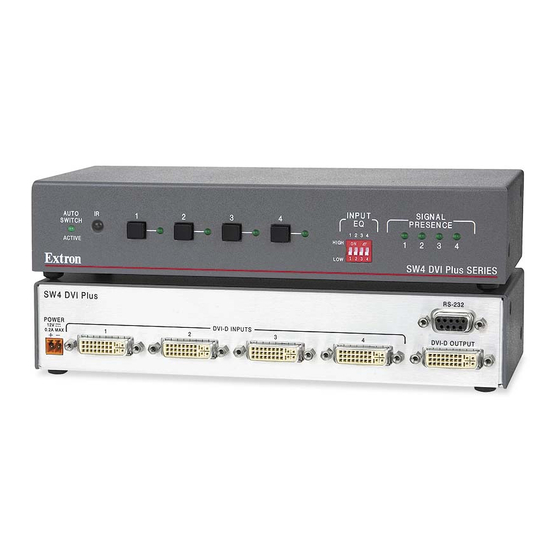
The following front panel illustrations apply to both the audio and non-audio versions of the SW DVI Plus. INPUT AUTO SIGNAL SWITCH PRESENCE HIGH ACTIVE SW2 DVI Plus SERIES Figure 14. SW2 DVI Plus Front Panel INPUT AUTO SIGNAL SWITCH PRESENCE 2 3 4 HIGH ACTIVE SW4 DVI Plus SERIES Figure 15. -
Page 19: Operations
Auto Switch Active LED — This LED lights when auto-input switching is enabled. (See “Enabling Auto-input Switching” in the “Installation” section for the procedure to set up auto-input switching.) IR receiver port — This sensor detects IR signals from the optional IR 102 remote control (see “Using the Optional IR 102 Remote Control”... -
Page 20: Using The Optional Ir 102 Remote Control
Input Selection Other ways to select an input include using SIS commands (see the commands in the Command and Response Table for SIS Commands, “Remote Configuration and Control” section) or the optional IR remote control (see “Using the Optional IR 102 Remote Control”). -
Page 21: Enabling Front Panel Lockout (Executive Mode)
Enabling Front Panel Lockout (Executive Mode) Front panel lock mode (executive mode) disables all front panel controls. Putting the switcher in this mode enhances security by protecting against inappropriate or accidental changes to settings. When the switcher is in lock mode, RS-232 and IR control remain available. - Page 22 User-assigned EDID mode In this mode, you can select an EDID file that is stored on the switcher at the factory. The selected EDID is stored at the inputs and is not overwritten; the switcher does not automatically obtain EDID information from the display. You may want to use this mode if there is a problem with automatic communication of the EDID information from the attached display, and you want to ensure that the correct information is stored on the inputs.
-
Page 23: Resetting
Resetting To reset the switcher to its factory default settings: Press and hold the Input 1 button while power is being applied to the unit. Continue holding the Input 1 button until the power-up sequence completes. NOTE: Resetting restores the EDID mode to automatic, with a resolution of 1024x768 @ 60 Hz. -
Page 24: Remote Configuration And Control
Remote Configuration and Control This section describes remote operation of the SW DVI Plus series. Topics include: • Using Simple Instruction Set (SIS) Commands Universal Switcher Control Program • • Updating Firmware Using Firmware Loader Using Simple Instruction Set (SIS) Commands The SW DVI Plus can be remotely set up and controlled via a host computer or other device (such as a control system) that is attached to the rear panel Remote/Auto-SW port. -
Page 25: Error Responses
Error Responses If the switcher is unable to execute a command it receives because the command is invalid or contains invalid parameters, the switcher returns an error response to the host. Error response codes and their descriptions are as follows: E01 –... -
Page 26: Command And Response Table For Sis Commands
Command and Response Table for SIS Commands ASCII Command Response Command Additional Description (Host to Unit) (Unit to Host) Input Selection Select video and audio input • All Select audio (if available) and video input = input number: 0 through number of inputs on the switcher. - Page 27 ASCII Command Response Command Additional Description (Host to Unit) (Unit to Host) EDID Minder X% ] Assign EDID to inputs EDID Edid A Select EDID file for all inputs. = EDID file location number (see below): 0 = Automatic mode (default): EDID of connected display is detected and passed to the inputs.
- Page 28 ASCII Command Response Command Additional Description (Host to Unit) (Unit to Host) Information Requests X@ ] Request information • A • F • Vmt • Amt Show the selected video inputs, audio inputs (audio models only), switch mode, video muting status, and audio muting status (audio models only).
-
Page 29: Universal Switcher Control Program
Universal Switcher Control Program The Windows-based Universal Switcher Control Program provides an additional method of configuring and operating the SW DVI Plus switcher. The program is compatible with Windows 2000, Windows XP, Windows 7, and higher versions. The software is provided on a DVD that is delivered with your SW DVI Plus unit. -
Page 30: Starting The Program
Figure 22. Software Button on the DVD Window Scroll to the Universal Switcher Control program and click the Install link at right. Figure 23. Universal Switcher Install Link on DVD Follow the on-screen instructions to install the software on your computer. By default, the installation of the Universal Switcher Control Program creates a directory at c:\Program Files\Extron\UnivSW , and it places the following four icons in it:... -
Page 31: Using The Help System
Figure 24. Universal Switcher Control Program Window Using the Help System For information on how to use the Universal Switcher control program and explanations of its features and functions, access the help program using any of the following methods: • On your desktop, click >... -
Page 32: Downloading The Sw Dvi Plus Firmware
On the next Download Center screen, locate Firmware Loader and click its Download link. Figure 25. Firmware Loader Download Link On the next screen, enter the requested information, then click the Download fw_loader_vnxnxn.exe button (where is the Firmware Loader version number). -
Page 33: Loading The Firmware To The Switcher
The Firmware Loader window opens with the Add Device window displayed in front. On the Add Device window, select your SW DVI Plus model from the Device Names drop-down menu ( SW2 DVI Plus Series SW4 DVI Plus Series SW6 DVI Plus Series SW8 DVI Plus Series... - Page 34 Click . If the connection is successful, appears in green in Connect SW DVI Plus Series figure 30 the Connected Device section, followed by a green check mark (see on the next page). Click the Browse button in the New Firmware File (Optional) section. On the Open window, navigate to the new firmware file, which has an extension, and double-click it.
- Page 35 On the Add Device window, the path to the new firmware file is displayed in the Path field. Figure 30. Path to the New Firmware File If this is the only device to which you are uploading firmware, click . The switcher information is added to the Devices section of the Firmware Loader window and the Add Device window closes.
- Page 36 If you want to remove a device from the Devices section, do the following: Click on the names of the devices to be deleted, to highlight them. Select from the menu. Remove Selected Devices Edit On the Remove Devices window, select or deselect any devices on the list as desired, then click Remove To remove all devices from the field, select...
-
Page 37: Reference Information
Reference Information • Specifications • Part Numbers Mounting the SW DVI Plus Switcher • Specifications NOTE: *Appropriate DVI-D to HDMI cables or adapters are required for HDMI signal input/output. NOTE: The SW DVI Plus Series are not HDCP compliant. Video Maximum data rate ...... - Page 38 Audio output Number/signal type ......1 stereo, balanced/unbalanced Connectors ........(1) 3.5 mm captive screw connector, 5-pole Impedance ........50 ohms unbalanced, 100 ohms balanced Maximum level (Hi-Z) ...... >+16.5 dBu, balanced; >8.2 dBV, unbalanced at 1% THD+N Maximum level (600 ohm) ....>+10.4 dBm, balanced; >7.1 dBm, unbalanced at 1% THD+N Control/remote —...
- Page 39 Mounting SW2 and SW4 models Rack mount ....... Yes, with optional rack shelf kit Back of the rack mountable with optional back-of-the-rack mounting kit Furniture mount ....Yes, with optional under-desk mounting kit SW6 and SW8 models ..... Rack mountable with included bracket kit Enclosure type ........
-
Page 40: Part Numbers
Part Numbers Included Parts These items are included with SW DVI Plus Series switcher: Included Parts Part Numbers SW2 DVI Plus 60-964-01 SW2 DVI A Plus 60-964-21 SW4 DVI Plus 60-965-01 SW4 DVI A Plus 60-965-21 SW6 DVI Plus 60-966-01... -
Page 41: Mounting The Sw Dvi Plus Switcher
Pay particular attention to supply connections other than direct connections to the branch circuit (for example, use of power strips). Rack mounting the SW2 DVI Plus and SW4 DVI Plus For optional rack mounting of the models with enclosures of 8.75 inches wide by... - Page 42 Standard 9.5-inch Deep Rack Shelf Back of the rack mounting The SW2 DVI Plus and the SW4 DVI Plus can also be mounted vertically to the front or rear rack supports, using the optional MBB 100 Back of the Rack Mounting Kit (part number 70-367-01) as follows: If rubber feet were previously attached to the bottom of the unit, remove them.
- Page 43 M AT R IX IE S IT C VI D H ER D IO Figure 36. Mounting an SW DVI Plus to a Back of the Rack Support Rack mounting the SW6 DVI Plus and SW8 DVI Plus For optional rack mounting of the models with enclosures 17.5 inches wide by 8.5 inches deep (six-input and eight-input models), use the provided MBD 149 mounting kit (part number 70-077-03) as follows: Attach the mounting brackets to the unit, using eight of the machine screws supplied...
-
Page 44: Furniture Mounting (Sw2 And Sw4 Dvi Plus Only)
Furniture Mounting (SW2 and SW4 DVI Plus Only) To mount an SW2 or SW4 DVI Plus switcher under a desk, table, or podium, use the optional MBU 123 Mini Under-Desk Mounting Kit (part number 70-212-01) as follows: If rubber feet were previously attached to the bottom of the unit, remove them. Remove the two screws from each side of the switcher. -
Page 45: Extron Warranty
Extron Warranty Extron Electronics warrants this product against defects in materials and workmanship for a period of three years from the date of purchase. In the event of malfunction during the warranty period attributable directly to faulty workmanship and/or materials, Extron Electronics will, at its option, repair or replace said products or components, to whatever extent it shall deem necessary to restore said product to proper operating condition, provided that it is returned within the warranty period, with proof of purchase and description of malfunction to: USA, Canada, South America,...