Table of Contents
Advertisement
AXMINSTER
Hobby
SERIES
508213
Leg Stand
508214
Sliding Table Kit
508212
R/H Extension Table
717540
Table Saw and Accessories
TS-250M 250mm
Basic Table Saw
Hole assembly instructions including leg
stand extension table and sliding table kits
Product Kit Codes
717540: TS-250M Table Saw and Accessories
508211: TS-250M Basic Saw
508213: TS-250M Leg Stand
508212: TS-250M R/H Extension Table Kit
508214: TS-250M Sliding Table Kit
Code 508211
508211
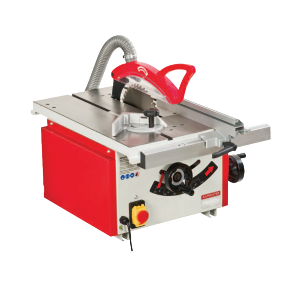
Basic Saw
Advertisement
Table of Contents

Related Manuals for Axminster TS-250M


Summary of Contents for Axminster TS-250M
- Page 1 508212 R/H Extension Table 508211 Basic Saw 717540 Table Saw and Accessories Product Kit Codes 717540: TS-250M Table Saw and Accessories 508211: TS-250M Basic Saw 508213: TS-250M Leg Stand 508212: TS-250M R/H Extension Table Kit 508214: TS-250M Sliding Table Kit...
-
Page 2: Declaration Of Conformity
Index of Contents Index of Contents Declaration of Conformity What’s Included 03-04 Optional Accessories 05-06 General Instructions for 230V Machines 07-08 Specific Instructions/Precaution for the Saw Table Specification Assembly 09-10-11-12-13-14-15-16-17-18 Illustration and Parts Description 19-20-21 Setup and Adjustments 22-23-24 Operating Instructions 25-26 Changing the Saw Blade 26-27... -
Page 3: What's Included
What’s Included Quantity Item Part Model Number MJ10-SB250 (Basic Table Saw Assembly) (Kit Code: 508211) 1 No Basic Table Saw 1 No Saw Guard with Flexible Hose 1 No Dust Extraction Moulding with four Phillips Screws 1 No Mitre Fence Assembly 1 No (Short) Rip Fence and Clamping Assembly 1 No... - Page 4 What’s Included Having unpacked your saw and its accessories please dispose of any unwanted packaging properly. The packaging is biodegradable. Basic Table Saw (Code: 508211)
-
Page 5: Optional Accessories
Optional Accessories Stand Assembly (Kit code: 508213) R/H Extension Table Assembly (Kit code: 508212) - Page 6 Optional Accessories Sliding Table Assembly (Kit code: 508214) Work clamp block Connecting block...
-
Page 7: General Instructions For 230V Machines
General Instructions for 230V Machines not use any solvents or cleaners, as these may cause Good Working Practices/Safety damage to any plastic parts or to the electrical components. Keep the work area as uncluttered as is The following suggestions will enable you to observe practical, this includes personnel as well as material. - Page 8 General Instructions for 230V Machines Check that blades are the correct type and size, are Above all, OBSERVE…. make sure you know what is undamaged and are kept clean and sharp, this will happening around you and USE YOUR COMMON SENSE.
-
Page 9: Specification
Specification Code 508211 Model TS-250M Basic Rating Hobby Power 1.5kW 230V 1ph Blade Dia/Bore 250mm/30mm Blade Tilt 0° to 45° Max Depth of Cut @ 45˚ 60mm Max Depth of Cut @ 90˚ 80mm Max Width of Cut with Fence... - Page 10 Assembly Mounting the Saw Bench to the Stand Optional Sliding Carriage Table (Kit Code 508214) 1). With assistance, place the Saw 1). Position one carriage support arm (V) to the Bench (A) onto the stand. Align the four underside of the cast iron saw bench (A), line up mounting holes at the base of the Saw the clearance holes (a) in the support arm with the Bench with the four mounting holes at...
- Page 11 Assembly NOTE: Only screw on the bolts just enough so they Make sure the wheels on carriage table engages are just below the surface of the threaded nut, see correctly onto the carriage arm rails, see fig 15. fig 11. Fig 14-15 4).
- Page 12 Assembly 7). Locate the two carriage arm stops (W4), loosen Fig 20-21 the domed nuts and slide the bolt heads into each end of the carriage arms ‘T’ slot. Tighten the nuts to ‘T’ Slot lock the stop in place, see fig 17. Fig 17 Connecting block Lift and shift handle...
- Page 13 Assembly Fig 23 Fig 26-27 Grub locking screw Lift and shift handle Fig 24 Angle fence stop Eccentric bush carriage table (Y), see figs 28-29. Tighten the three lift & shift handles to lock the angle fence in position. Fig 25 Note: The fence can also be used at the rear of the sliding carriage table if you prefer to push the timber against the fence.
- Page 14 Assembly 5). Locate the flip over stop (T) and slide it into the Fig 32-33 T-slot on top of the angle fence (R), see fig 30. Tighten Height mechanism shaft the butterfly knob. Fig 30 Tilt mechanism shaft Mitre Fence Locate the Mite fence assembly (D) and slide it into one of the saw tables “T”...
- Page 15 Assembly Fig 37-38 Optional Extension Table (Kit Code 508212) NOTE: KIT CODE 508211 COMES WITH THE FENCE SUPPORTING ARM ONLY AND DOES NOT INCLUDE THE REAR SUPPORTING ARM! 1). Put to hand six M6 x 25mm Phillip head screws with square nuts (O2), remove the nuts and place the screws into the three holes to the front and rear of the main saw table (A).
- Page 16 Assembly 3). Put to hand six M6 x 16mm Phillip head screws Fig 44 with square nuts (O3), remove the nuts and place safely aside. Slot the screws into each of the 6 holes on the extention table lip (M), replace the square nuts, see figs 41-42.
- Page 17 Assembly Rip Fence Fig 50-51 NOTE: THIS ASSEMBLY OLNY APPLIES IF YOU HAVE PURCHASED KIT CODE: 508212 1). Remove the fence clamp assembly from the rip fence (E) by lossening the clamping bolt to the base of the asssebly. using a 10mm socket/spanner. Locate Clamp asssembly the rip fence (Q), slot the steel square clamp into the T-slot to the end of the rip fence and tighten the bolt,...
- Page 18 Assembly 3). Line up the holes in the extraction moulding (C), Fig 55 with the threaded holes to the rear of the saw table (A) and secure in place with the Phillips screw and washers, see fig 53. 4). Slide the remaining hose clip over one end of ‘T’...
-
Page 19: Illustration And Parts Description
Illustration and Parts Description TS-250M Table Saw Kit Code 717540 Basic Table Saw Kit Code 508211 Part Description Part Description Basic Table Saw Extension Table Saw Guard with Flexible Hose Long Fence and Table Extension Rail Arms 50-100mm Dust Extraction Moulding (see page 20) - Page 20 Illustration and Parts Description Clamp Work clamp block (A) and connecting block (B) Flip over stop assembly...
- Page 21 Illustration and Parts Description Clamping knob Shroud Scale Pointer Mitre fence assembly NVR ON/OFF switch with emergency stop shroud Adjusting screw Pointer Scale Tilt operating handle Tilt scale pointer and adjusting screw Tilt mechanisum clamp Scale Rise and fall operating handle and the clamping handle for the tilt mechanisum Carriage table scale for measuring set angles...
-
Page 22: Setup And Adjustments
Setup and Adjustments The Riving Knife Adjusting the Rip Fence to the Blade 1). Raise the saw blade to its highest point and The fence assembly must be parallel to the saw remove the saw blade guard, see fig 34 on page 14. blade for producing accurate cuts. - Page 23 Setup and Adjustments 4). The rip fence (E-Q) can be repositioned to face Adjusting the Pivot the opposite direction for guiding thin timber pieces Release the locking handle (A), see fig 67-68 the saw through. can be angled up to a maximum of 45˚ by turning the hand wheel (G6), see figs 68-69.
- Page 24 Setup and Adjustments Setting the Blade Alignment 4). Place the rule to the opposite end of the blade and take a further reading, see fig 73. If the blade is not cutting 100% true, the blade is out of alignment. Follow the instructions below on how 6).
-
Page 25: Mains Supply
Operating Instructions Fig 76 NOTE: BEFORE USING YOUR SAW, GO ROUNDAND MAKE SURE EVERYTHING IS SECURE, FASTENED DOWN, THAT ALL TOOLS ARE CLEARED AWAY FROM THE WORK AREA! CHECK: THE BLADE FOR SHARPNESS,MISSINGTEETH, Fig 77 RESINBUILDUP ECT., CLEAN IF NECESSARY. CHECK THE BLADE IS SECURELY CLAMPED IN PLACE (I.E. -
Page 26: Blade Guard
Operating Instructions Fig 79 Fig 80 THE BLADE IS SET AT AN ANGLE LESS THAN 90˚ DEGREES FOR BEVEL CUTS HOLD THE WORK FIRMLY LOCK THE MITRE BLADE GUARD FENCE AND HOLD THE WORK FIRMLY Changing the Saw Blade 1). Raise the saw blade to its highest point, remove Fig 82 the saw blade guard, remove the four Hex screws that secure the table insert, place carefully aside and... -
Page 27: Maintenance
Changing the Saw Blade 6). Check the old blade for sharpness, missing teeth, resin build up, etc., clean if necessary and send for refurbishment/resharpening if required. If the blade is not to be re-sharpened, clean and pack away in its storage case. -
Page 28: Parts Breakdown/List
Parts Breakdown/List... - Page 29 Parts Breakdown/List Part No Description Q’TY Ball bearing Set screw Ball bearing Shaft C-Spring Hand wheel Shaft Flat head screw M5 Sharp Press block Supporting plate Screw Washer Motor C-Spring Washer Motor guidance plate Arbor Washer 6 Washer T-nut M6 Set screw Sawing base Set screw...
- Page 30 Parts Breakdown/List...
-
Page 31: Wiring Diagram
Parts Breakdown/List Arbor Scale Plate Guide Supporting rear Bolt Washer Tap screw 4 x12 Nut M20 Flat head screw M4 x 8 Table Right protection plate Cover Flat head screw M4 x 8 Screw Safety screen (right) Screw Left protection plate Tap screw 4 x 24 Scale Lock bolt... - Page 32 Hobby, Trade, Industrial, Engineer, Air Tool & Axcnc Technology Series machines It’s probably the most comprehensive FREE guarantee ever- buy with confidence from Axminster! So sure are we of the quality, we cover all parts and labour free of charge for three years! •...
Need help?
Do you have a question about the TS-250M and is the answer not in the manual?
Questions and answers