
Related Manuals for DeLonghi Domino DE302IB


Summary of Contents for DeLonghi Domino DE302IB
- Page 1 INSTALLATION and SERVICE INSTRUCTIONS USE and CARE INSTRUCTIONS DOMINO INDUCTION HOB model DE302IB distributed by DèLonghi Pty Ltd...
-
Page 2: Product Label
Dear Customer, Thank you for having purchased and given your preference to our product. The safety precautions and recommendations reported below are for your own safety and that of others. They will also provide a means by which to make full use of the features offered by your appliance. -
Page 3: Before Using For The First Time
BEFORE USING FOR THE FIRST TIME • Read the instructions carefully before installing and using the appliance. • After unpacking the appliance, make sure it is not damaged. In case of doubt, do not use the appliance and contact your supplier or a qualified engineer. •... -
Page 4: Important Safeguards & Recommendations
IMPORTANT SAFEGUARDS & RECOMMENDATIONS • Do not carry out any cleaning or maintenance without first disconnecting the appliance from the electrical supply. • During and after use of the hob, certain parts will become hot. Do not touch hot parts. •... -
Page 5: Features And Technical Data
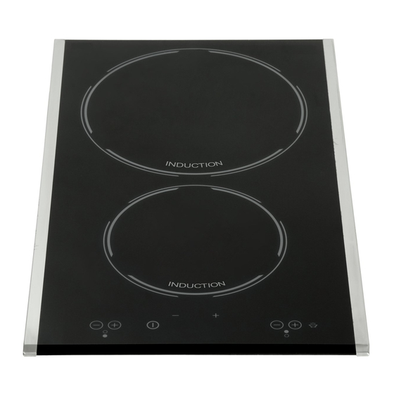
FEATURES AND TECHNICAL DATA Fig. 1.1 Electrical insulation Class I COOKING ZONES 1. Induction cooking zone Ø 140 mm - 1400 W 2. Induction cooking zone Ø 210 mm - 2200 W (3000 W with Booster function) TOUCH-CONTROL DESCRIPTION 3. ON/OFF key 4. -
Page 6: Use Of Induction Hob
USE OF INDUCTION HOB Notes: – Each selection (by pressing one of the keys) is indicated by an acoustic signal (beep). – User interface initial calibration: this feature is for the keyboard calibration, to adapt the sensibility of the keys to the final mechanical, environmental and user conditions. -
Page 7: Thermal Protection
THERMAL PROTECTION The induction cooktop is fitted with safety devices to protect the electronic system and each cooking zone from overheating. OVERHEATING OF COOKING ZONE – Cooking zone OFF: the cooking zone display shows “ ” and “ ” alternat- ing or just “... - Page 8 The ceramic cooktop is fitted with induction cooking zones. These zones, shown by painted disks on the ceramic surface, are controlled by a touch control system. INDUCTION COOKING SYSTEM When your induction hob is switched on and a cooking zone has been selected, the electronic circuits produce induced currents that instantaneously heat the bottom of the pan which then transfers this heat to the food.
- Page 9 HOW TO TURN THE TOUCH CONTROL ON AND OFF Switching ON Press the key and keep it pressed until the touch control is lighted. The displays of the cooking zones read “ ”. Notes: – If the safety key-lock protection is active, the touch control can be turned ON only after having deactivated this protection.
- Page 10 POWER IGNITION AND ADJUSTMENT OF A COOKING ZONE To turn ON a cooking zone the touch control must be switched ON (see sec- tion “How To Turn the Touch Control ON and OFF”). Press the key and keep it pressed until the desired power level, ranging between is set.
- Page 11 BOOSTER FUNCTION REAR COOKING ZONE ONLY This function allows the cooking zone to operate at the Booster maximum power (above the nominal power) for maximum 10 minutes; it could be used, for exam- ple, to rapidly heat up large amount of water.
- Page 12 SAFETY KEY-LOCK TO PROTECT CHILDREN This function locks the touch-control keys against unwanted activation. To activate the key-lock press the key ; the indicator light above the key symbol will light up. – Cooking zone/s operating (power level already set) - with the key-lock protec- tion active it is only possible to switch off the cooktop.
- Page 13 PROGRAM FOR AUTOMATIC SWITCHING OFF OF ONE COOKING ZONE This function permits to set a timer from minutes for automatic turning OFF of one cooking zone only. Note: It is not possible to set this pro- gram for both the cooking zones. With the touch control switched ON: –...
- Page 14 OPERATION TIME LIMIT OF COOKING Cooking zone Operation ZONES power level time limit Each cooking zone is automatically switched OFF after a maximum preset 10 hours time if no operation is performed. The maximum preset time limit depends 5 hours on the set power level, as illustrated in this schedule.
- Page 15 ERROR CODE ON THE DISPLAY/S If an error message appears on the display/s (the display/s show/s “ ” and another character alternating - e.g. “ ” and “ ”, “ ” and “ ”, ..) : 1. Disconnect the cooktop from the mains.
-
Page 16: Cleaning And Maintenance
CLEANING AND MAINTENANCE CLEANING THE CERAMIC HOB Before you begin cleaning make sure that the hob is switched off. • Remove spillages and other types of incrustations. • Dust or food particles can be removed with a damp cloth. • If you use a detergent, please make sure that it is not abrasive or scouring. Abrasive or scouring powders can damage the glass surface of the hob. -
Page 17: Advice For The Installer
ADVICE FOR THE INSTALLER... -
Page 18: Installation
INSTALLATION CAUTION: • This appliance shall only be serviced by authorized personnel. • This appliance is to be installed only by an authorised person according to the cur- rent local regulations and in observation of the manufacturer’s instructions. • Incorrect installation, for which the manufacturer accepts no responsibility, may cause personal injury of damage. - Page 19 This cooktop can be built into a working surface 30 to 40 mm thick and 600 mm deep. In order to install the ceramic hob into the kitchen fixture, a hole with the dimensions shown in figure 4.1 has to be made, keeping in consideration the following: •...
- Page 20 FASTENING THE COOKTOP Each cooktop is supplied with a set of tabs and screws to fasten it on units with a work- ing surface from 3 to 4 cm deep. The kit includes 4 tabs A and 4 self-threading screws B (fig. 4.4). •...
-
Page 21: Electrical Connection
ELECTRICAL CONNECTION IMPORTANT: Installation must be carried out according to the manufacturer’s instructions. Incorrect installation may cause harm and damage to people, ani- mals or property, for which the manufacturer accepts no responsibility. Before carrying out any work on the electrical section of the appliance, it must be disconnected from the mains. - Page 22 CONNECTING OF THE POWER SUPPLY CABLE • Unhook the terminal board cover by inserting a screwdriver into the two hooks A (fig. 5.1). • Open the cable gland by unscrewing screw F (fig. 5.3), unscrew the terminal screws and remove the cable. •...
- Page 23 Descriptions and illustrations in this booklet are given as simply indicative. The manufacturer reserves the right, considering the characteristics of the models described here, at any time and without notice, to make eventual necessary modifications for their construction or for commercial needs.
- Page 24 cod. 1103762 - ß1...
Need help?
Do you have a question about the Domino DE302IB and is the answer not in the manual?
Questions and answers