
Related Manuals for DeLonghi DEGMATIK90


Summary of Contents for DeLonghi DEGMATIK90
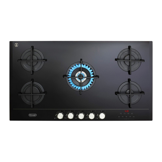
- Page 1 DE ’ L O N G H I C OO KING INSTALLATION and SERVICE INSTRUCTIONS USE and CARE INSTRUCTIONS D EG MATI K 90 BUILT-IN GAS ON GLASS COOKING HOBS distributed by DeLonghi Australia Pty Ltd DeLonghi New Zealand Ltd...
-
Page 2: Product Label
Dear Customer, Thank you for having purchased and given your preference to our product. The safety precautions and recommendations reported below are for your own safety and that of others. They will also provide a means by which to make full use of the features offered by your appliance. -
Page 3: Important Safety Precautions And Recommendations
IMPORTANT SAFETY PRECAUTIONS AND RECOMMENDATIONS IMPORTANT: This appliance is designed and manufactured solely for the cooking of domestic (household) food and is not suitable for any non domestic application and therefore should not be used in a commercial environment. The appliance guarantee will be void if the appliance is used within a non domestic environment i.e. - Page 4 CAUTION: this appIiance must only be installed in a permanently • ventilated room in compliance with the applicable regulations. • Do not carry out cleaning or maintenance operations on the appliance without having previously disconnected it from the electric power supply. •...
- Page 5 To avoid burns and scalds, young children should be kept away. – • Make sure that electrical cables connecting other appliances in the proximity of the cooktop cannot come into contact with the hob. WARNING: Unattended cooking on a hob with fat or oil can be •...
-
Page 6: Installation
INSTALLATION CAUTION: ■ Important: The use of suitable protective clothing/gloves is recommended when handling or cleaning of this appliance. ■ This appliance must be installed in accordance with these installation instructions, local gas fitting regulations, municipal building codes, water supply regulations, electrical wiring regulations, - Gas Installations and ony other relevant statutory regulations. - Page 7 3. The wire which is coloured brown must be connected to the terminal marked “L” (Live) or “A” (Active) or coloured Red. ■ A suitable isolating switch providing full disconnection from the mains power supply (under overvoltage category III conditions) shall be incorporated in the permanent wiring, mounted and positioned to comply with the local wiring rules and regulations.
- Page 8 CLEARANCES Installation clearances and protection of combustible surfaces shall comply with the current local regulations e.g. AS/NZS5601.1 (latest edition) - Gas Installations code. Figure 2a The thermal protection barrier must • removable with the use of a tool for installation and service; •...
- Page 9 From top of countertop (**) Between the back edge of the cut-out and the back of the countertop. (***) From the side edge of the cut-out to any vertical combustible surface. If this distance is less than 200 mm, the surface shall be protected (in accordance with AS/NZS5601.1) to a height of not less than 150 mm above the hob for the full dimension (width or depth) of the cooking surface area.
-
Page 10: Fastening The Cooktop
FASTENING THE COOKTOP Figure 3a Each cooktop is provided with an installation kit including brackets and screws for fastening the cooktop to benches from 30 to 40mm thick. The kit includes four “F” type brackets (for the front of the cooktop), three “R” type brackets (for the rear of the cooktop) and seven self-threading screws “S”. -
Page 11: Gas Supply
GAS SUPPLY Gas connection for ■ This appliance is suitable for use NATURAL GAS with Natural Gas or ULPG (Check the “gas type” sticker attached to the Gas inlet pipe appliance). ■ For Natural Gas the gas supply must be regulated to obtain a pressure of 1 kPa with the triple-ring (TR) burner operating at the maximum. - Page 12 Customer Service Centre should be called to obtain the nearest authorized Delonghi Service Agent. Where the appliance data plate cannot be easily read with the appliance in the...
- Page 13 TABLE FOR THE CHOICE OF THE INJECTORS Natural Gas ULPG Test Point Pressure [kPa] 2.75 Injector Injector Orifice Orifice BURNER Consumption Consumption Dia. Dia. [MJ/h] [MJ/h] [mm] [mm] Auxiliary (AUX) 0.92 4.20 0.56 4.20 Semi-rapid (SR) 1.17 6.60 0.70 6.20 Rapid (R) 1.54 11.75...
- Page 14 and replace with test point adaptor Auxiliary, semi-rapid and rapid burner (see figs. 4a, 4b). ■ If the cooktop is suitable for use with Universal LPG and must be converted for use with Natural gas, before connecting to the gas main remove the appliance test point adaptor and replace with gas regulator (see figs.
- Page 15 MINIMUM BURNER SETTING ADJUSTMENT Check whether the flame spreads to all burner ports when the burner is lit with the gas tap set to the minimum position. If some ports do not light, increase the minimum gas rate setting. Check whether the burner remains lit even when the gas tap is turned quickly from the maximum to the minimum position.
-
Page 16: Controls Description
USE and CARE CAUTION: ■ This appliance must be used only for the task it has explicitly been designed for, that is for domestic cooking of foodstuffs. Any other form of usage is to be considered as inappropriate and therefore dangerous. Do not use this appliance as a space heater. ■... -
Page 17: Important Notes
DESCRIPTION OF TOUCH-CONTROLS Child lock safety button (buttons lock) Timer display decrease button Timer display increase button Cooking end programmer/cooking timer setting button Front left cooking zone button Rear left cooking zone button Central cooking zone button Rear right cooking zone button Front right cooking zone button 10. -
Page 18: Using Gas Burners
■ If after relighting the burner, the flame is still abnormal, turn the burner off and contact our Customer Service Centre to obtain the nearest authorized Delonghi Service Agent. ■ In the case of a mains failure light the burner with a match or lighted taper. -
Page 19: Lighting The Burners
LIGHTING THE BURNERS ignite burner, following instructions are to be followed: Press in the corresponding knob and turn counter-clockwise (fig. 10) to the full flame position marked by the “ ” symbol (fig. 9); press and hold the knob to light the burner (the green indicator light on the knob will blink to show that burner ignition is in progress). - Page 20 IMPORTANT NOTE: The following functions are only enabled when the hob is supplied by the electrical mains. If electrical power is not present these functions are not available. OPERATION TIME LIMIT OF THE COOKING ZONES If no operations are carried out, all cooking zones are switched off automatically after a maximum operating time of 6 hours.
- Page 21 PROGRAM FOR AUTOMATIC SWITCHING OFF OF A COOKING ZONE This function makes it possible to program a cooking time from 1 minute to 3 hours 59 minutes, in order to switch off one or more cooking zones automatically. With the burner lit: ■...
- Page 22 COOKING TIMER SET-UP The cooking timer emits an audible notification signal after a maximum cooking time of 9 hours 59 minutes. To activate this function: 0.00 ■ Press the button (the timer shows “ ” in blinking mode and also the related indicator light blinks).
- Page 23 COOKING HINTS FOR GAS HOBS ■ The burner must be chosen according to the diameter of the pans and energy required. ■ The largest can be used for boiling, to seal meat or foods that are cooked quickly, and the smallest for stews and sauces.
- Page 24 Figure 13 WOK STAND (figs. 14 - 15) This special grille for woks should be placed over the pan-rest for the triple-ring compact, triple ring or Dual burner (depending on models). Warning: ■ The flat-bottomed pans are to be placed directly onto the pan-support. ■...
- Page 25 Do not place anything, e.g. flame tamer, asbestos mat, between pan and pan support as serious damage to the appliance may result. Do not remove the pan support and enclose the burner with a wok stand as this will concentrate and deflect heat onto the hotplate.
-
Page 26: Cleaning And Maintenance
CLEANING and MAINTENANCE GENERAL ADVICE ■ Before you begin cleaning, you must ensure that the appliance is switched off and disconnected from the electrical power supply. ■ Important: The use of suitable protective clothing/gloves is recommended when handling or cleaning of this appliance. ■... -
Page 27: Enamelled Parts
ENAMELLED PARTS ■ All the enamelled parts must be cleaned with a sponge and soapy water only or other non-abrasive products. ■ Dry preferably with a soft cloth. ■ If acid substances such as lemon juice, tomato conserve, vinegar etc. are left on the enamel for a long time they will etch it, making it opaque. - Page 28 BURNERS ■ These parts can be removed and cleaned with appropriate products. ■ After cleaning, the burners and their flame spreaders must be well dried and correctly replaced. ■ Check that the electrode/s “S” (figs. 18, 20) next to each burner is/are always clean to ensure trouble-free sparking.
- Page 29 Figure 18 Figure 19 Figure 20 Figure 21 Figure 22...
-
Page 30: Pan Supports
PAN SUPPORTS ■ These parts can be removed and cleaned with appropriate products. ■ After cleaning, they must be well dried and correctly replaced (fig. 23). ■ It is very important to check that the pan supports have been correctly positioned. Failure to do so can cause serious problems. -
Page 31: Service And Maintenance
SERVICE AND MAINTENANCE If the ignition spark fails to ignite or does not light the gas, check the following items before calling our Customer Service Centre to obtain the nearest Authorised Delonghi Service Agent: ■ Burner is reassembled and located correctly. - Page 32 Descri pt i ons an d ill ustrati ons in this booklet a re giv en as simpl y ind icat ive. T h e ma nuf a ct ur er r es erv es the right, consider ing t he cha ract eri stics o f t he models described here, at any time and without notice, to make eventual necessary mo d ifi cat i on s f or the ir constr ucti on or for com merc ial n eeds.
Need help?
Do you have a question about the DEGMATIK90 and is the answer not in the manual?
Questions and answers