
Related Manuals for Dell PowerEdge H730P


Summary of Contents for Dell PowerEdge H730P
- Page 1 Dell PowerEdge RAID Controller (PERC) H730P For Dell PowerEdge R920 Systems User’s Guide Regulatory Model: UCPA-901 and UCPB-900...
- Page 2 WARNING: A WARNING indicates a potential for property damage, personal injury, or death. Copyright © 2014 Dell Inc. All rights reserved. This product is protected by U.S. and international copyright and intellectual property laws. Dell ™...
-
Page 3: Table Of Contents
Contents 1 Overview........................11 ......................12 Supported Operating Systems ....................12 Getting Started With Your PERC Card ........................12 Related Documentation 2 Features........................15 .........................15 T10 Protection Information ..........................15 Enabling T10 PI ..........................16 Disabling T10 PI ........................16 Secure Firmware Update ......................16 Improved RAID 10 Configuration ........................ - Page 4 ............33 Pre-Installation Requirements For Windows Driver Installation ..........33 Creating The Device Driver Media For Windows Driver Installation Downloading Drivers From The Dell Systems Service And Diagnostic Tools Media For ............................34 Windows .........34 Downloading Drivers From The Dell Support Website For Windows ......34...
- Page 5 ........................51 Deleting Virtual Disks ........................51 Deleting Disk Groups ......................51 Clearing The Configuration ..................52 BIOS Configuration Utility Menu Options ......................52 Virtual Disk Management ........................54 Virtual Disk Actions ..................55 Physical Disk Management (PD Mgmt) ........................55 Physical Disk Actions ............................56 Rebuild ....................56 Controller Management (Ctrl Mgmt)
- Page 6 ......................... 67 Deleting A Security Key ......................67 Creating Secured Virtual Disks ....................67 Securing Pre-Existing Virtual Disks ....68 Importing Or Clearing Secured Foreign Configurations And Secure Disk Migration ........................69 Instant Secure Erase 7 Troubleshooting...................... 71 ..................71 BIOS Configuration Utility Error Messages .......................
- Page 7 ..................79 Fatal Error Or Data Corruption Reported ....................79 Physical Disk Displayed As Blocked .....................79 Multiple Disks Become Inaccessible ....................80 Rebuilding A Failed Physical Disk ............80 Virtual Disk Fails During Rebuild Using A Global Hot Spare ..........80 Virtual Disk Fails During Rebuild Using A Dedicated Hot Spare ........
- Page 8 ......................... 89 SyntaxDescription ............................. 90 Result ......................... 90 Deleting Preserved Cache ......................... 90 SyntaxDescription ............................. 90 Result ....................90 Displaying Expansion Information ......................... 90 SyntaxDescription ............................. 90 Result ....................... 91 Displaying Foreign Configuration ..........................91 SyntaxDescription ..............................91 Result ......................91 Importing Foreign Configuration ..........................91 SyntaxDescription ..............................91...
- Page 9 ..........................101 Contacting Dell .........................101 Documentation Feedback ....................101 Locating Your System Service Tag...
-
Page 11: Overview
Complies with serial-attached SCSI (SAS) 3.0 providing up to 12 Gb/sec throughput. • Supports Dell-qualified serial-attached SCSI (SAS) hard drives, SATA hard drives, and solid-state drives (SSDs). NOTE: Mixing 512–byte native and 512–byte emulated drives are allowed. But mixing 512–byte and 4KB native block size drives are not allowed. -
Page 12: Supported Operating Systems
Deploying The PERC Card. Boot to the operating system. Download and install the drivers and firmware for the PERC H730P card. See Driver Installation. Create virtual disks and specify RAID levels for your hard drives using any of the utilities mentioned below: •... - Page 13 NOTE: For all PowerEdge documentation, go to dell.com/poweredgemanuals. NOTE: For all PowerVault documentation, go to dell.com/powervaultmanuals. Your product documentation includes, Dell PowerEdge RAID Controller (PERC) H730P User’s Guide For Dell PowerEdge R920 Systems. The User’s Guide discusses features, installation, management, and...
-
Page 15: Features
T10 Protection Information T10 Protection Information (PI) is an end-to-end data integrity feature of the PERC H730P card. When PI is enabled, the PERC H730P provides additional protection against silent data corruption, and ensures that incomplete and incorrect data do not overwrite good data. -
Page 16: Disabling T10 Pi
NOTE: An even number of drives is required to create RAID 10 virtual disks. 4KB Block Size Disk Drives PERC H730P card supports 4KB block size disk drives, which enables you to efficiently use the storage space. NOTE: Mixing 512–byte native and 512–byte emulated drives in a virtual disk is allowed. But, mixing 512–byte and 4KB native block size drives in a virtual disk is not allowed. -
Page 17: Configured Spin Down Delay
During full initialization, the host cannot access the virtual disk. You can start a full initialization on a virtual disk by using the Slow Initialize option in the Dell OpenManage storage management application. For more information on using the BIOS Configuration Utility to perform a full initialization, see Initializing Virtual Disks. -
Page 18: Background Initialization
Background Initialization (BGI) is an automated process that writes the parity or mirror data on newly created virtual disks. BGI does not run on RAID 0 virtual disks. You can control the BGI rate in the Dell OpenManage storage management application. Any change in the BGI rate does not take effect until the next BGI run. -
Page 19: Using Disk Roaming
Solid State Drives (SSD). The Dell PowerEdge RAID Controller (PERC) H730P supports FastPath. To enable FastPath on a virtual disk the Dell PowerEdge RAID Controller (PERC) H730P cache policies need to be set to Write-Through and No Read Ahead. This enables FastPath to use the proper data path through the controller based on command (read/write), IO size, and RAID type. -
Page 20: Migrating Virtual Disks
To migrate virtual disks from PERC H710, H710P, or H810 to PERC H730P: Turn off the system. Move the physical disks from PERC H710, H710P, or H810 card to the PERC H730P card. Boot the system and import the foreign configuration that is detected. You can do one of the following: •... -
Page 21: Conditions Under Which Forced Write-Back With No Battery Is Employed
Conditions Under Which Forced Write-Back With No Battery Is Employed CAUTION: It is recommended that you use a power backup system when forcing Write-Back to ensure there is no loss of data if the system suddenly loses power. Write-Back mode is available when you select Force WB with no battery. When Forced Write-Back mode is selected, the virtual disk is in Write-Back mode even if the battery is not present. - Page 22 See the following table for a list of RLM/OCE possibilities. Table 2. RAID Level Migration Source RAID Target RAID Number of Number of Capacity Description Level Level Physical Disks Physical Disks Expansion (Beginning) (End) Possible RAID 0 RAID 0 2 or more Increases capacity by adding disks.
-
Page 23: Fault Tolerance
NOTE: The total number of physical disks in a disk group cannot exceed 32. You cannot perform RAID level migration and expansion on RAID levels 10, 50, and 60. Fault Tolerance The PERC H730P card supports the following: • Self Monitoring and Reporting Technology (SMART) •... -
Page 24: Patrol Read
The Patrol Read feature is designed as a preventative measure to ensure physical disk health and data integrity. Patrol Read scans and resolves potential problems on configured physical disks. The Dell OpenManage storage management application can be used to start Patrol Read and change its behavior. -
Page 25: Physical Disk Failure Detection
NOTE: The persistent hot spare slot feature is disabled by default. The PERC H730P card can be configured so that the system backplane or storage enclosure disk slots are dedicated as hot spare slots. This feature can be enabled using the Dell OpenManage storage management application. -
Page 26: Controller Cache Preservation
Creating A Non-RAID Disk To create a non-RAID disk, perform the following steps in the BIOS Configuration Utility (<Ctrl> <R>): In the Virtual Disk Mgmnt screen, use the arrow keys to highlight PERC H730P Adapter or Disk Group #. Press <F2>. -
Page 27: Deploying The Perc Card
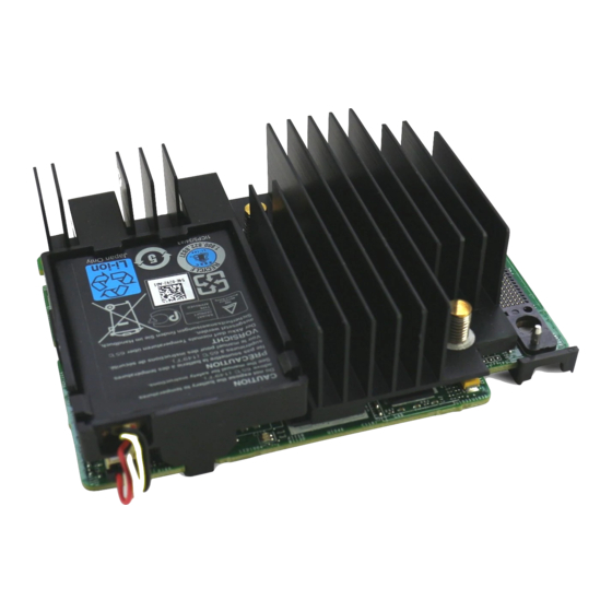
NOTE: For information on removing and reinstalling system parts, see the Dell PowerEdge R920 Owner's Manual at dell.com/poweredgemanuals. This section provides a set of high level installation and removal instructions for the PERC H730P card. PERC H730P Card Features Figure 1. Features Of PERC H730P Card... -
Page 28: Removing The Perc H730P Card
Damage due to servicing that is not authorized by Dell is not covered by your warranty. Read and follow the safety instructions that came with the product. -
Page 29: Installing The Perc H730P Card
Open the system. Remove the NDC riser. Lift the clamp attached to power supply bay and locate the PERC H730P card connector on the system board. CAUTION: To prevent damage to the card, you must hold the card by its edges only. -
Page 30: Cabling The Perc H730P Card
13. Reconnect the system to its electrical outlet and turn the system on, including any attached peripherals. Cabling The PERC H730P Card This section provides information about cabling the PERC H730P card on the the Dell PowerEdge R920 systems. Figure 3. Cabling Diagram–2.5 Inch (x4) SAS/SATA Backplane with PERC H730P Card SAS cable connector on the PERC H730P card 2. - Page 31 SAS connector on the backplane Figure 4. Cabling Diagram–2.5 Inch (x24) SAS/SATA Backplane with PERC H730P Card SAS (A&B) cable connector on the PERC H730P PERC H730P card card system board...
- Page 32 backplane jumper cable connector on the backplane...
-
Page 33: Driver Installation
Driver Installation The Dell PowerEdge RAID Controller (PERC) H730P card requires software drivers to operate with the supported operating systems. This chapter contains the procedures for installing the drivers for the PERC H730P card. NOTE: For more information on VMware ESX drivers, see the VMware ESX documentation at dell.com/support/manuals. -
Page 34: Downloading Drivers From The Dell Systems Service And Diagnostic Tools Media For Windows
Downloading Drivers From The Dell Systems Service And Diagnostic Tools Media For Windows To download drivers from the Dell Systems Service and Diagnostic Tools media: Insert the Dell Systems Service and Diagnostics Tools media in your system. The Welcome to Dell Service and Diagnostic Utilities screen is displayed. -
Page 35: Installing Windows Server 2008/2008 R2/2012 For A New Raid Controller
SCSI and RAID Controller. NOTE: In Windows Server 2008, Windows Server 2008 R2, and Windows Server 2012, the PERC H730P card is listed under Storage Controllers. Double-click the RAID controller for which you want to update the driver. -
Page 36: Updating The Linux Driver
For more information, see dell.com/support. Updating The Linux Driver NOTE: PERC H730P drivers support PERC 5, PERC 6, PERC 7, and PERC 8 family controllers and do not require separate driver installations. Use the procedures in this section to update the driver for Linux. To ensure that you have the current version of the driver, download the updated Linux driver from dell.com/support. -
Page 37: Installing Or Updating The Rpm Driver Package With Kmp Support
Installing Or Updating The RPM Driver Package With KMP Support NOTE: This procedure is applicable for SUSE Enterprise Linux 11 SP2. Perform the following steps to install the RPM package with KMP support: Uncompress the gzipped tarball driver release package. Install the driver package using the command: rpm –ihv kmpmegaraid_ sas- <version>.rpm. -
Page 39: Management Applications For Perc Cards
BIOS utilities. The graphical user interface (GUI) is wizard-driven with features for novice and advanced users, and detailed online help. Using the Dell OpenManage storage management application, you can protect your data by configuring data-redundancy, assigning hot spares, or rebuilding failed physical disks. -
Page 40: Bios Configuration Utility
NOTE: You can access PERC H700, H800, H310, H710, H710P, H810P, or H730P cards from the same BIOS if the controller firmware is 6.2.0-0013 or later. NOTE: If you enter the option ROM of PERC H730P, you can access the option ROM of both H730P and H810 adapters. -
Page 41: Menu Navigation Controls
Menu Navigation Controls The following table displays the menu keys you can use to move between the different screens in the BIOS Configuration Utility (<Ctrl> <R>). Table 3. Menu Navigation Keys Notation Meaning and Use Example right- Use the right-arrow key to open a submenu, Start →... -
Page 42: Setting Up Virtual Disks
Notation Meaning and Use Example <Shift> Press <Shift> <Tab> to move the cursor to the Press <Shift> <Tab> to move the cursor from <Tab> previous control on a dialog or page. Sort By to the previously selected PD in thePD Mgmt screen. <Ctrl>... - Page 43 NOTE: The default hard drive cache policy for a virtual disk with SAS hard drives is disabled and virtual disk with SATA hard drives is enabled. The Virtual Disk parameter cannot be changed in the BIOS Configuration Utility (<Ctrl> <R>). Use Dell OpenManage Storage Management for the hard drive cache setting operation.
-
Page 44: Virtual Disk Management
Select a controller, and press <Enter>. The Virtual Disk Management screen is displayed for the selected controller. Use the arrow keys to highlight PERC H730P Adapter or Disk Group #. Press <F2>. A list of available actions is displayed. -
Page 45: Selecting Virtual Disk Parameters
12. Set the virtual disk size in the VD Size field. The virtual disk size is displayed in GB format. 13. Press <Tab> to access the VD Name field, and type a virtual disk name. 14. Press <Tab> to move the cursor to Advanced settings 15. -
Page 46: Checking Data Consistency
A pop-up window is displayed indicating that the virtual disk has been initialized. Repeat the procedures from step 1 to step 3 to configure another virtual disk. NOTE: The PERC H730P card supports up to 64 virtual disks per controller. The currently configured virtual disks display on the screen. - Page 47 Perform the following steps to import or clear foreign configurations: During bootup, press <Ctrl> <R> when prompted by the BIOS screen. The VD Mgmt screen is displayed by default. On the VD Mgmt screen, highlight the Controller #. Press <F2> to display the available actions. Navigate to the Foreign Config option and press the right arrow key to display the available actions: a.
- Page 48 A Break Mirror is performed only on RAID 1 arrays. It provides a way to 'split' the mirror and spin-down one of the hard disks, which can then be imported into the configuration of a different PERC H730P controller. This can be a useful way to:...
-
Page 49: Importing Or Clearing Foreign Configurations Using The Foreign Configuration View Screen
• Create a disk image that can be imported and booted on a different system. • Assist in software or configuration testing, where half of the mirror can be removed to ensure configuration consistency. NOTE: The Break Mirror operation is not available within the booted operating system environment. -
Page 50: Managing Dedicated Hot Spares
To manage the preserved cache: On the VD Mgmt screen, click on a controller icon. Press <F2> to display the available actions. Select Manage Preserved Cache. A message is displayed advising you to import the foreign configuration before you discard the preserved cache to avoid losing data belonging to the foreign configuration. -
Page 51: Deleting Virtual Disks
Deleting Virtual Disks NOTE: You cannot delete a virtual disk during an initialization. NOTE: Warning messages appear stating the effect of deleting a virtual disk. Click OK twice to complete the virtual disk deletion. Perform the following steps in the BIOS Configuration Utility (<Ctrl> <R>) to delete the virtual disks: Press <Ctrl>... -
Page 52: Bios Configuration Utility Menu Options
BIOS Configuration Utility Menu Options The first menu that is displayed when you access the BIOS Configuration Utility <Ctrl> <R> is the main menu screen. It lists the controller, controller number, and other information, such as the slot number. On the screen, you can use the arrow keys to select the RAID controller you want to configure. Press <Enter>... - Page 53 Menu Item Selected in Left Panel Information Displayed in Right Panel • Number of free segments • Number of dedicated hot spares • Security property of the Disk Group Virtual Disks Disk Group # Properties: • Number of virtual disks (VD) •...
-
Page 54: Virtual Disk Actions
RAID level 1, 5, 6, 10, 50, or 60 is used. The PERC virtual disk H730P card automatically corrects any differences found in the data. Display or update Displays the properties of the selected virtual disk. You can modify the cache virtual disk write policy and read policy from the menu. -
Page 55: Physical Disk Management (Pd Mgmt)
Max Device Link Rate • Negotiated Link Rate • Dell Certified Disk Physical Disk Actions The following table describes the actions you can perform on physical disks. For procedures that can be used to perform the actions, see Physical Disk Management (PD Mgmt). -
Page 56: Rebuild
The factors include the rebuild rate setting, virtual disk stripe size, virtual disk read policy, virtual disk write policy, and the amount of workload placed on the storage subsystem. For information on getting the best rebuild performance from your RAID controller, see the documentation at dell.com/ support/manuals. -
Page 57: Foreign Configuration View
Table 10. Controller Management Options Option Description Select the option to enable the controller BIOS. If Enable Controller BIOS the boot device is on the RAID controller, the BIOS must be enabled. Disable the BIOS to use other boot devices. In a multiple controller environment, you can enable the BIOS on multiple controllers. -
Page 58: Physical Disk Management
Physical Disk Management Setting LED Blinking The LED blinking option indicates when physical disks are being used to create a virtual disk. You can choose to start or stop the LED blinking. Following the below procedures to set LED Blinking: Press <Ctrl>... -
Page 59: Replacing An Online Physical Disk
Press the down-arrow key to select Remove Hot Spare from the list of actions and press <Enter>. The physical disk is changed to the Ready state. The status of the physical disk is displayed under the heading State. NOTE: Try to use physical disks of the same capacity in a specific virtual disk. If you use physical disks with different capacities in a virtual disk, all physical disks in the virtual disk are treated as if they have the capacity of the smallest physical disk. -
Page 60: Performing A Manual Rebuild Of An Individual Physical Disk
The virtual disk is undergoing a background initialization process. Would you like to stop the operation and proceed with the <full initialization/quick initialization/consistency check> instead? Click Yes to stop the BGI and start the requested operation or No to allow the BGI to continue. Performing A Manual Rebuild Of An Individual Physical Disk CAUTION: If a physical disk is a member of a disk group that contains multiple virtual disks and one of the virtual disks is deleted when a rebuild operation is in progress, the rebuild operation... -
Page 61: Enabling Boot Support For A Bios-Enabled Controller
Enabling Boot Support For A BIOS-Enabled Controller Press <Ctrl> <N> to access the Ctrl Mgmt menu screen. Press <Tab> to move the cursor to the Select Boot Device in the Settings box. Press the down-arrow key to display a list of virtual disks. Use the down-arrow key to highlight a virtual disk. -
Page 62: Disabling Auto Import
Disabling Auto Import To disable auto import: Use the spacebar to de-select Enable Auto Import. Select Apply and press <Enter>. The auto import is disabled. Restoring Factory Default Settings You can use the Ctrl Mgmt menu screen to restore the default settings for the options in the Settings box. -
Page 63: Configuration Options
Change Controller Properties—Updates controller properties and/or restores factory defaults for the controller. NOTE: For PowerEdge R920 system using PERC H730P, the option will read Change link Speed to Gen 3. – Boot Error Handling: Handles the errors found at boot. -
Page 64: Virtual Disk Management
Virtual Disk Management The Virtual Disk Management menu can be used to create and manage virtual disks on the controller. The following functions can be performed under Virtual Disk Management. Each of these functions is its own selectable menu option. •... -
Page 65: Security Key And Raid Management
There is one security key per controller. You can manage the security key under Local Key Management (LKM). The key can be escrowed in to a file using Dell OpenManage storage management application. The security key is used by the controller to lock and unlock access to encryption-capable physical disks. -
Page 66: Creating A Security Key
NOTE: Under LKM, you are prompted for a passphrase when you create the key. Creating A Security Key NOTE: There is no passphrase backup option when you create a security key; you need to remember your passphrase. Perform the following steps to create a security key on the controller: During the host system boot up, press <Ctrl>... -
Page 67: Deleting A Security Key
Press <Tab> and select OK to accept the settings and to exit the window. Select Cancel to exit if you do not want to change the security key on the controller. NOTE: If there is an existing configuration on the controller, it is updated with the new security key. -
Page 68: Importing Or Clearing Secured Foreign Configurations And Secure Disk Migration
NOTE: If you are importing secured and unsecured virtual disks, you are prompted to resolve the secured foreign configuration first. NOTE: The PERC H730P card needs to have a security key present before being able to import a secured virtual disk. -
Page 69: Instant Secure Erase
Press <Tab> and select OK to finish importing the secured foreign configuration or select Cancel to exit this menu. If you select Cancel for the secured foreign import, the disks remain inaccessible until imported or instant secure erased. See Instant Secure Erase. -
Page 71: Troubleshooting
Troubleshooting To get help with your Dell PowerEdge RAID Controller (PERC) H730P, you can contact your Dell Technical Service representative or see dell.com/support. BIOS Configuration Utility Error Messages The controller BIOS read-only memory (ROM) provides Int 13h functionality (disk I/O) for the virtual disks connected to the controller. -
Page 72: Previous Configuration Of Disks Removed Error Message
Corrective Check the cable connections and fix any issues. Restart the system. If there are no Action: cable problems, press any key or <C> to continue. Previous Configuration Of Disks Removed Error Message Error Message: All of the disks from your previous configuration are gone. If this is an unexpected message, then please power off your system and check your cables to ensure all disks are present. -
Page 73: Bios Disabled Error Message
<Y> to continue. Adapter At Baseport Not Responding Error Message Error Message: Adapter at Baseport xxxx is not responding, where xxxx is the baseport of the controller. Corrective Contact Dell Technical Support. Action:... -
Page 74: Offline Or Missing Virtual Drives With Preserved Cache Error Message
Offline Or Missing Virtual Drives With Preserved Cache Error Message Error Message: There are offline or missing virtual drives with preserved cache. Please check the cables and ensure that all drives are present. Press any key to enter the configuration utility. Probable The controller preserves the dirty cache from a virtual disk if the disk becomes Cause:... -
Page 75: Memory Or Battery Problem Error Message
Corrective Allow the battery to charge fully to resolve this problem. If the problem persists, the Action: battery or controller memory may be faulty. Contact Dell Technical Support. Firmware Fault State Error Message Error Message: Firmware is in Fault State. -
Page 76: Previous Configuration Cleared Or Missing Error Message
If you insert a physical disk that was previously a member of a virtual disk in the system, and that disk’s previous location has been taken by a replacement disk through a rebuild, you must manually remove the foreign configuration flag of the newly inserted disk. -
Page 77: Memory Errors
The controller logs an event to the controller’s internal event log and a message during POST is displayed indicating a multi-bit error has occurred. NOTE: In case of a multi-bit error, contact Dell Technical Support. Preserved Cache State The controller preserves the dirty cache from a virtual disk if the virtual disk becomes offline or is deleted because of missing physical disks. -
Page 78: Failure To Delete Security Key
Installing The PERC H730P Card. Physical Disk Issues Physical Disk In Failed State Issue: One of the physical disks in the disk array is in the failed state. Corrective Update the PERC cards to the latest firmware available on dell.com/support. Action:... -
Page 79: Unable To Rebuild A Fault Tolerant Virtual Disk
Offline state due to a cable pull or power loss situation, the virtual disk is imported in its Optimal state without a rebuild occurring. NOTE: You can use the BIOS Configuration Utility (<Ctrl> <R>) or Dell OpenManage storage management application to perform a manual rebuild of multiple physical disks. For information on... -
Page 80: Rebuilding A Failed Physical Disk
You must insert a physical disk with enough storage in the subsystem before rebuilding the physical disk. NOTE: You can use the BIOS Configuration Utility (<Ctrl> <R>) or Dell OpenManage storage management application to perform a manual rebuild of an individual physical disk. For information... -
Page 81: Smart Errors
NOTE: For information about where to find reports of SMART errors that could indicate hardware failure, see the Dell OpenManage storage management documentation at dell.com/support/ manuals. Smart Error Detected On A Physical Disk In A Redundant Virtual Disk Issue: A SMART error is detected on a physical disk in a redundant virtual disk. -
Page 82: Source Disk Fails During Replace Member Operation
Source Disk Fails During Replace Member Operation Issue: The source disk fails during the Replace Member operation. Corrective If the source data is available from other disks in the virtual disk, the rebuild begins Action: automatically on the target disk, using the data from the other disks. Target Disk Fails Issue: The target disk fails. -
Page 83: Driver Does Not Auto-Build Into A New Kernel
Driver Does Not Auto-Build Into A New Kernel Issue: Driver does not auto-build into a new kernel after customer updates. Corrective This error is a generic problem for Dynamic Kernel Module Support (DKMS) and Action: applies to all DKMS-enabled driver packages. This issue occurs when you perform the following steps: Install a DKMS-enabled driver package. - Page 84 Figure 5. Disk Carrier LED Indicators activity LED status LED...
-
Page 85: Using Perc Cli
Using PERC CLI This topic introduces the concept of using the Dell PowerEdge RAID Controller Command Line Interface (CLI) method for managing RAID controllers, performing a variety of controller and enclosure specific operations, and configuring the PERC cards. Using CLI Commands From Windows Command Prompts... -
Page 86: Checking Controller Availability
Commands Description Set a particular value to a property Start background operation start Stop background operation stop Pause background operation pause Resume background operation resume Downloads file to given device download Expands size of given drive expand Inserts new drive for missing insert Downgrades the controller transform... -
Page 87: Displaying Controllers
Host name = WIN-RFV0S1VAILB Operating System = Windows Server 2012 System Overview : =============== ------------------------------------------------------------------------- Ctl Model Ports DNOpt VNOpt ASOs ------------------------------------------------------------------------- Adapter ------------------------------------------------------------------------- Displaying Controllers Syntax perccli show ctrlcount Description Displays the number of controllers detected in the server. Result Status Code = 0 Status = Success... -
Page 88: Result
Displays the current list of information about the adapter, virtual disks, drivers and so on. Result Status Code = 0 Status = Success Description = none Product Name = PERC H730P Adapter Serial Number = 38E005K SAS Address = 5b8ca3a0f78d9000 Mfg. Date = 08/28/13 System Time = 11/30/2013 05:12:51 Controller Time = 11/30/2013 05:13:29 FW Package Build = 25.2.0.0014... -
Page 89: Checking For Preserved Cache
----------------------------------------------------------------------------- DG Arr Row EID:Slot DID Type State Size PI SED DS3 FSpace ----------------------------------------------------------------------------- RAIDS Opt1 1.635 TB dflt dflt RAIDS Opt1 1.635 TB dflt dflt 32:0 DRIVE Onln 558.375 GB dflt dflt 32:1 DRIVE Onln 558.375 GB dflt dflt 32:3 DRIVE Onln 558.375 GB... -
Page 90: Result
Result Controller = 0 Status = Success Description = None ------------ State ------------ Missing ------------ Deleting Preserved Cache Syntax perccli /c0/v1 delete preservedcache Description Deletes the available preserved cache. Result Controller = 0 Status = Success Description = Virtual Drive preserved Cache Data Cleared Displaying Expansion Information Syntax perccli /c0/v0... -
Page 91: Displaying Foreign Configuration
Displaying Foreign Configuration Syntax perccli /c0/fall show Description Displays the entire foreign configuration for specified controller. Result Controller = 0 Status = Success Description = Operation on foreign configuration Succeeded FOREIGN CONFIGURATION : ===================== --------------------------------------- DG EID:Slot Type State Size NoVDs --------------------------------------- RAID0 Frgn 372.0 GB... -
Page 92: Result
Result Controller = 0 Status = Success Description = None BBU_Info : ======== ---------------------- Property Value ---------------------- Type Voltage 3 mV Current 0 mA Temperature 32 C Battery State Optimal ---------------------- BBU_Firmware_Status : =================== ------------------------------------------------- Property Value ------------------------------------------------- Charging Status None Voltage Temperature... -
Page 93: Displaying Physical Drive Details For The Specified Slot In The Controller
Battery backup charge time 0 hour(s) ------------------------------------- BBU_Capacity_Info : ================= ------------------------------------------------------ Property Value ------------------------------------------------------ Relative State of Charge 100% Absolute State of charge 0% Remaining Capacity 407 mAh Full Charge Capacity 407 mAh Run time to empty Battery is not being charged Average time to empty 33 min Average Time to full... -
Page 94: Result
Description Displays detailed information about the physical drive. Also, provides information related to device attribute, settings, and port information of a physical drive for the specified slot in the controller. Result Controller = 0 Status = Success Description = Show Drive Information Succeeded. Drive /c0/e32/s4: ================ -------------------------------------------------------------------------------... -
Page 95: Displaying Boot Drive For The Controller
Secured = Yes Locked = No Needs EKM Attention = No PI Eligible = Yes Drive is formatted for PI = Yes PI type = 2 Number of bytes of user data in LBA = 4 KB Certified = Yes Wide Port Capable = No Port Information : ================... -
Page 96: Result
Description Sets the specified virtual drive as the boot drive. During the next reboot, the BIOS looks for a boot sector in the specified virtual drive. Result Controller = 0 Status = Success Description = None Detailed Status : =============== ---------------------------------------------- Property Value... -
Page 97: Appendix: Raid Description
Summary Of RAID Levels Following is the RAID levels supported by PERC H730P cards: • RAID 0 uses disk striping to provide high data throughput, especially for large files in an environment that requires no data redundancy. -
Page 98: Disk Mirroring
For example, in a four-disk system using only disk striping (used in RAID 0), segment 1 is written to disk 1, segment 2 is written to disk 2, and so on. Disk striping enhances performance because multiple physical disks are accessed simultaneously, but disk striping does not provide data redundancy. Figure 6. - Page 99 The parity data is distributed across all the physical disks in the system. If a single physical disk fails, it can be rebuilt from the parity and the data on the remaining physical disks. RAID level 5 combines distributed parity with disk striping. Parity provides redundancy for one physical disk failure without duplicating the contents of the entire physical disks.
-
Page 101: Getting Help
Documentation Feedback If you have feedback for this document, write to documentation_feedback@dell.com. Alternatively, you can click on the Feedback link in any of the Dell documentation pages, fill out the form, and click Submit to send your feedback. Locating Your System Service Tag Your system is identified by a unique Express Service Code and Service Tag number.
Need help?
Do you have a question about the PowerEdge H730P and is the answer not in the manual?
Questions and answers