Bosch VIP X1 Installation And User Manual
Hide thumbs
Also See for VIP X1:
- Installation and operating manual (144 pages) ,
- Quick installation manual (12 pages) ,
- Brochure & specs (5 pages)
Table of Contents
Advertisement
Advertisement
Table of Contents

Related Manuals for Bosch VIP X1


Summary of Contents for Bosch VIP X1
- Page 1 VIP X1/VIP X2 – Network video server...
- Page 2 Copyright This user guide is the intellectual property of Bosch Security Systemsand is protected by copyright. All rights reserved. No part of this document may be reproduced or transmitted for any purpose, by whatever means, electronic or mechanical, without the express written permission of Bosch Security Systems.
-
Page 3: Table Of Contents
EN | 3 VIP X1/VIP X2 | Installation and User Guide Contents Chapter 1 Preface Conventions ......... 5 Intended use. - Page 4 EN | 4 Installation and User Guide | VIP X1/VIP X2 Hardware connections between video servers....84 Establishing the connection ......84 Closing the connection .
-
Page 5: Chapter 1 Preface
EN | 5 VIP X1/VIP X2 | Installation and User Guide Preface This user guide is intended for persons responsible for the installation and operation of the VIP X. International, national and any regional regulations regarding electronics must be followed at all times. Relevant knowledge of network technology is required. -
Page 6: Intended Use
85521 Ottobrunn Germany www.bosch-sicherheitssysteme.de EU Directives The VIP X1 and VIP X 2 network video servers comply with the requirements of EU Directives 89/336 (Electromagnetic Compatibility) and 73/23, amended by 93/68 (Low Voltage Directive). Rating plate For exact identification, the model name and serial number are inscribed on the rating plate on the bottom of the housing. -
Page 7: Chapter 2 Safety Information
– if foreign matter has infiltrated the unit, – after long storage under adverse conditions or – after exposure to extraordinary transport stress. In such cases, have the unit checked by Bosch Security Systems. Bosch Security Systems | 2005-05 | V1.0 Safety information... -
Page 8: Installation And Operation
EN | 8 Installation and User Guide | VIP X1/VIP X2 Installation and operation The relevant electrical regulations and guidelines must be complied with at all times during installation. Relevant knowledge of network technology is required to install the unit. -
Page 9: Chapter 3 Product Description
Note Check that the delivery is complete and in perfect condition. Arrange for the unit to be checked by Bosch Security Systems if you find any damage. System requirements for setup Computer with Windows 2000/XP operating system, access to network and Microsoft Internet Explorer (version 6.0 or later) -
Page 10: Configuration Requirements
EN | 10 Installation and User Guide | VIP X1/VIP X2 Configuration requirements Computer with Windows 2000/XP operating system, network access and Microsoft Internet Explorer web browser (version 6.0 or later) Computer with Windows 2000/XP operating system, network access and... -
Page 11: Overview Of Functions
Overview of functions Network video server The VIP X is an ultra-compact network video server for one (VIP X1) or two (VIP X2) connected video sources. Its primary function is to encode video and control data for transmission over an IP network. With its encoding in MPEG-4... -
Page 12: Remote Control
EN | 12 Installation and User Guide | VIP X1/VIP X2 Multicast In suitably configured networks, the multicast function enables simultaneous, real time transmission to multiple receivers. The prerequisite for this is that the UDP and IGMP V2 protocols are implemented on the network. - Page 13 Multicast function for simultaneous picture transmission to multiple receivers One analog BNC video input FBAS (PAL/NTSC) on the VIP X1 Two analog BNC video inputs FBAS (PAL/NTSC) on the VIP X2 Video encoding using international MPEG-4 standard...
-
Page 14: Front Panel Connections
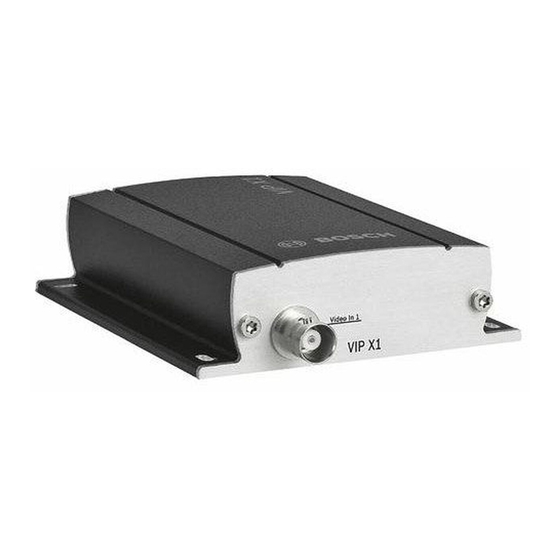
EN | 14 Installation and User Guide | VIP X1/VIP X2 Front panel connections VIP X1 1 Video input Video In BNC jack for connection of video source VIP X2 2 Video input Video In 1 BNC jack for connection of video source... -
Page 15: Rear Panel Connections
EN | 15 VIP X1/VIP X2 | Installation and User Guide Rear panel connections 4 USB interface for future expansion of functions 5 Factory-reset button to restore default settings 6 Terminal block for alarm inputs, relay output, serial interface and power supply... - Page 16 EN | 16 Installation and User Guide | VIP X1/VIP X2 Product description Bosch Security Systems | 2005-05 | V1.0...
-
Page 17: Chapter 4 Installation
The ambient temperature must be between 0 and + 50 C (VIP X1) or between 0 and +40 C (VIP X2), relative humidity may not exceed 80 %. -
Page 18: Connections
Installation and User Guide | VIP X1/VIP X2 Connections Cameras Depending on the device used, you can connect one (VIP X1) or two video sources (VIP X2). Any cameras or other video sources that produce a standard PAL or NTSC signal are suitable. - Page 19 EN | 19 VIP X1/VIP X2 | Installation and User Guide configuration, an alarm sensor can, for example, trigger an automatic connection between the VIP X and a remote location. A voltage free make contact or switch can be used as an actuator.
-
Page 20: Turning On/Off
EN | 20 Installation and User Guide | VIP X1/VIP X2 Turning on/off Mains connection The VIP X includes a mains power supply with four primary adapters and terminal block. The VIP X does not have a power switch. The unit is ready for operation as soon as it is connected to the voltage feed. -
Page 21: Setup Using A Terminal Program
EN | 21 VIP X1/VIP X2 | Installation and User Guide Setup using a terminal program Data terminal You can connect a data terminal to the VIP X for setup and local control. The data terminal consists of a computer with terminal software. You can use the supplied configuration cable to make the connection (for pin assignment of the orange terminal block, see page 94). - Page 22 EN | 22 Installation and User Guide | VIP X1/VIP X2 Command entry After the connection has been established, you must log on to VIP X. You can then access the main menu. You can call up additional submenus and functions using the on-screen commands.
- Page 23 EN | 23 VIP X1/VIP X2 | Installation and User Guide – Enter the desired IP address and press Enter. The new IP address will be shown. – Use the commands displayed for any additional settings required. Note The new IP address and a new subnet mask or gateway address will only be valid after restarting.
- Page 24 EN | 24 Installation and User Guide | VIP X1/VIP X2 Installation Bosch Security Systems | 2005-05 | V1.0...
-
Page 25: Chapter 5 Configuration Using A Web Browser
EN | 25 VIP X1/VIP X2 | Installation and User Guide Configuration using a Web Browser Connecting The integrated HTTP server allows the unit to be configured over the network with a Web browser. This option is significantly more comprehensive and convenient than configuration using a terminal program and also offers you the option of displaying live video images. - Page 26 LIVEPAGE with the video image will appear. Note Depending on whether you are using a VIP X1 or a VIP X2, the screen display may differ slightly from that shown above. If the connection is not established, the maximum number of possible connections may already have been reached.
-
Page 27: Choosing The Configuration Mode
EN | 27 VIP X1/VIP X2 | Installation and User Guide Password protection in VIP X If the VIP X is password-protected against unauthorized access, a corresponding message and a prompt to enter the password will appear when you attempt to access protected areas. - Page 28 47) and the unit overview (see Unit overview, page 29) is opened. Note Depending on whether you are using a VIP X1 or a VIP X2, the screen display may differ slightly from that shown above. Configuration using a Web Browser...
-
Page 29: Unit Overview
EN | 29 VIP X1/VIP X2 | Installation and User Guide Unit overview The unit overview gives you a graphical overview of the individual areas of the configuration. The individual configuration parameters are grouped and displayed in separate windows. You can access the individual areas directly. - Page 30 EN | 30 Installation and User Guide | VIP X1/VIP X2 Encoder settings For encoding the video signal, you can select two profiles for each encoder (video input) and change the presets for the profiles. Selecting a profile You can adapt the MPEG-4 data transmission to the operating environment (for example network structure, bandwidth, data structures).
- Page 31 EN | 31 VIP X1/VIP X2 | Installation and User Guide Profile 4: DSL For DSL connections at 500 kBit/s, resolution 352 x 288/240 pixels Profile 5: ISDN (2B) For ISDN connections via two B channels, resolution 352 x 288/240 pixels...
-
Page 32: Changing Profiles
EN | 32 Installation and User Guide | VIP X1/VIP X2 Changing profiles You can change individual parameter values within a profile and the name. You can switch between profiles by clicking the associated tabs. Warning! The profiles are rather complex. They include a number of parameters that interact with one another. - Page 33 EN | 33 VIP X1/VIP X2 | Installation and User Guide For complex images or frequent changes of image content due to frequent movements, this limit can temporarily be exceeded as far as the value you enter in the Max. data rate field.
- Page 34 EN | 34 Installation and User Guide | VIP X1/VIP X2 Video resolution: Here, you can select the desired resolution for the MPEG-4 video image. The following resolutions are available: QCIF 176 × 144/120 pixels 352 × 288/240 pixels 1/2 D1 352 ×...
-
Page 35: System Settings
EN | 35 VIP X1/VIP X2 | Installation and User Guide System settings Various basic data for the VIP X can be set or selected here. Unit identification Unit name: The unit can be assigned a name to assist in identifying it. The name simplifies the management of multiple devices in more extensive systems, for example using the VIDOS software. - Page 36 EN | 36 Installation and User Guide | VIP X1/VIP X2 Note Proper password protection is only guaranteed if all higher authorization levels are also protected with a password. For example, if a live password is assigned, a service and a user password should also be set. When assigning passwords, you should always start from the highest authorization level.
- Page 37 EN | 37 VIP X1/VIP X2 | Installation and User Guide Language Website language: Select the language for the user interface here. Date and Time Date format: Choose the desired date format here (Europe: DD.MM.YYYY; USA: MM.DD.YYYY; Japan: YYYY/MM/DD). Unit date and time: If there are a number of devices operating in your system or network, it is important to synchronize their internal clocks.
-
Page 38: Version Information
EN | 38 Installation and User Guide | VIP X1/VIP X2 Version information The hardware and firmware version numbers are for information only and cannot be altered. Keep a record of these numbers in case technical assistance is required. Hardware version: The hardware version number of the VIP X is displayed. -
Page 39: Alarm Settings
EN | 39 VIP X1/VIP X2 | Installation and User Guide Alarm settings Here, you can make the settings for the alarm sources and alarm connections. Alarm sources You can configure the possible alarm triggers for the VIP X (for example the alarm inputs). -
Page 40: Alarm Connections
EN | 40 Installation and User Guide | VIP X1/VIP X2 Alarm connections You can select the response of the VIP X in case of an alarm. In case of an alarm, the VIP X can automatically establish a connection to a predefined IP address. -
Page 41: Network Settings
EN | 41 VIP X1/VIP X2 | Installation and User Guide Note For automatic connections, always Stream 2 is transmitted. Take this into account when assigning the profile (see page 31). Network settings Here, you can specify network addresses and configure multiple connections. - Page 42 EN | 42 Installation and User Guide | VIP X1/VIP X2 Gateway address: If you want the unit to establish a connection to a remote location in a different subnet, enter the IP address of the gateway here. Otherwise, this field can remain empty (0.0.0.0).
- Page 43 EN | 43 VIP X1/VIP X2 | Installation and User Guide Multicasting In addition to a 1:1 connection between an encoder and a single receiver (unicast), the VIP X can enable multiple receivers to receive the video signal from an encoder simultaneously. This is either done by duplicating the data...
- Page 44 EN | 44 Installation and User Guide | VIP X1/VIP X2 Multicast address video 1 / Multicast address video 2: Enter a valid multicast address for each stream from the relevant encoder (video input) to be operated in multicast mode (duplication of the data streams in the network).
- Page 45 EN | 45 VIP X1/VIP X2 | Installation and User Guide COM1 settings You can configure the parameters of the RS232/485 serial interface to meet your requirements. Note If the VIP X is working in multicast mode (see page 43), the first remote location to establish a video connection to the unit is also assigned the transparent data connection.
-
Page 46: Stop Bits
EN | 46 Installation and User Guide | VIP X1/VIP X2 Stop bits: Select the number of stop bits per character. Parity check: Select the type of parity check. Interface mode: Select the desired protocol for the serial interface. Half-duplex mode: Choose the setting appropriate for your application. -
Page 47: Configuration Menu
– Click one of the links in the sub-menu. The corresponding page will be opened. Note Depending on whether you are using a VIP X1 or a VIP X2, the screen display may differ slightly from that shown above. Bosch Security Systems | 2005-05 | V1.0... -
Page 48: Unit Identification
EN | 48 Installation and User Guide | VIP X1/VIP X2 Making changes Each configuration page shows the current settings. The settings can be changed by entering new values or by selecting a predefined value in a list field. – Click Set after each change to save it. - Page 49 EN | 49 VIP X1/VIP X2 | Installation and User Guide Password A VIP X is generally protected by a password to prevent unauthorized access to the unit. You can use various authorization levels (User name:) to limit access. Note Proper password protection is only guaranteed if all higher authorization levels are also protected with a password.
- Page 50 EN | 50 Installation and User Guide | VIP X1/VIP X2 Confirm password: Re-enter the new password to rule out typing mistakes. Note The new password is then saved by clicking the Set button. You should therefore click the Set button immediately after entering and confirming the password, even if you also want to assign a password to another user name.
-
Page 51: Time Settings
EN | 51 VIP X1/VIP X2 | Installation and User Guide Time server The VIP X can receive the time signal from a time server using the time server protocol (RFC 868) and then use it to set the internal clock. The device calls up the time signal automatically every ten minutes. -
Page 52: Display Stamping
EN | 52 Installation and User Guide | VIP X1/VIP X2 Display stamping Various overlays or "stamps" in the video image provide important supplementary information. These overlays can be enabled individually and arranged on the image in a clear manner. -
Page 53: Picture Settings
EN | 53 VIP X1/VIP X2 | Installation and User Guide Displayed alarm message: Enter the message to be displayed for an alarm. It can contain up to 31 characters. Video watermarking: Choose On if the video images transmitted are to be "watermarked". After activation, all images will be marked with a small green rectangle. - Page 54 EN | 54 Installation and User Guide | VIP X1/VIP X2 Brightness (0...255): You can use this function to tailor the brightness of the video image to your working environment. MPEG-4 encoder For encoding the video signal, you can select two profiles for each encoder (video input) and change the presets for the profiles.
- Page 55 EN | 55 VIP X1/VIP X2 | Installation and User Guide Profile 4: DSL For DSL connections at 500 kBit/s, resolution 352 x 288/240 pixels Profile 5: ISDN (2B) For ISDN connections via two B channels, resolution 352 x 288/240 pixels...
- Page 56 EN | 56 Installation and User Guide | VIP X1/VIP X2 Changing profiles You can change individual parameter values within a profile and the name. You can switch between profiles by clicking the associated tabs. Warning! The profiles are rather complex. They include a number of parameters that interact with one another.
- Page 57 EN | 57 VIP X1/VIP X2 | Installation and User Guide For complex images or frequent changes of image content due to frequent movements, this limit can temporarily be exceeded as far as the value you enter in the Max. data rate field.
- Page 58 EN | 58 Installation and User Guide | VIP X1/VIP X2 Video resolution: Here, you can select the desired resolution for the MPEG-4 video image. The following resolutions are available: QCIF 176 × 144/120 pixels 352 × 288/240 pixels 1/2 D1 352 ×...
- Page 59 EN | 59 VIP X1/VIP X2 | Installation and User Guide Video input You can activate the 75 Ohm terminating resistor for each video input on the VIP X. To transmit the video signal, the terminating resistor must be deactivated.
-
Page 60: Alarm Sources
EN | 60 Installation and User Guide | VIP X1/VIP X2 Alarm sources You can configure the possible alarm triggers for the VIP X (for example the alarm inputs). Alarm input 1 … Alarm input 4: Select the option On in order to activate the alarm via the corresponding external alarm sensor. - Page 61 EN | 61 VIP X1/VIP X2 | Installation and User Guide Alarm connections You can select the response of the VIP X in case of an alarm. In case of an alarm, the VIP X can automatically establish a connection to a predefined IP address (compatible MPEG-4 compatible hardware receiver or computer with reception software).
- Page 62 EN | 62 Installation and User Guide | VIP X1/VIP X2 Note For automatic connections, always Stream 2 is transmitted. Take this into account when assigning the profile (see page 55). Relay You can configure the switching behavior of the relay output. Open switch relay (normally closed contact) or a closed switch relay (normally open contact) can be specified.
- Page 63 EN | 63 VIP X1/VIP X2 | Installation and User Guide Relay follows: For each number, enter the corresponding IP address for the desired remote location. No relay triggering by events Connection Triggering if any connection is established Video loss alarm...
- Page 64 EN | 64 Installation and User Guide | VIP X1/VIP X2 COM1 You can configure the parameters of the RS232/485 serial interface to meet your requirements. Note If the VIP X is working in multicast mode (see page 43), the first remote location to establish a video connection to the unit is also assigned the transparent data connection.
- Page 65 EN | 65 VIP X1/VIP X2 | Installation and User Guide Parity check: Select the type of parity check. Interface mode: Select the desired protocol for the serial interface. Half-duplex mode: Choose the setting appropriate for your application. Bosch Security Systems | 2005-05 | V1.0...
- Page 66 EN | 66 Installation and User Guide | VIP X1/VIP X2 Network The settings on this page are used to integrate the unit into an existing network. Warning! Changes to the IP address, subnet mask or gateway address are transferred to the unit by clicking Set. However, they only take effect after the unit is restarted.
- Page 67 EN | 67 VIP X1/VIP X2 | Installation and User Guide Warning! Multicast operation is only possible with the UDP protocol. The TCP protocol does not support multicast connections. Note The MTU value in UDP mode is 1514 bytes. Ethernet link type: If the VIP X is connected to the network via a switch, both devices must have the same preset network connection type.
- Page 68 EN | 68 Installation and User Guide | VIP X1/VIP X2 Multicasting In addition to a 1:1 connection between an encoder and a single receiver (unicast), the VIP X can enable multiple receivers to receive the video signal from an encoder simultaneously. This is either done by duplicating the data...
- Page 69 EN | 69 VIP X1/VIP X2 | Installation and User Guide Multicast address video 1 / Multicast address video 2: Enter a valid multicast address for each stream from the relevant encoder (video input) to be operated in multicast mode (duplication of the data streams in the network).
- Page 70 EN | 70 Installation and User Guide | VIP X1/VIP X2 Version information The hardware and firmware version numbers are for information only and cannot be altered. Keep a record of these numbers in case technical assistance is required. Hardware version: The hardware version number of the VIP X is displayed.
- Page 71 EN | 71 VIP X1/VIP X2 | Installation and User Guide Livepage configuration In this window, you can adapt the appearance of the LIVEPAGE to meet your requirements. Options are provided here to display various information and operating elements in addition to the video image.
- Page 72 EN | 72 Installation and User Guide | VIP X1/VIP X2 Device logo URL: Enter the path for a suitable image for the upper part of the window (banner) here. The image can be stored on a local computer, a local network or at an Internet address.
- Page 73 EN | 73 VIP X1/VIP X2 | Installation and User Guide File for system log: Enter the path for saving the system log here. – If necessary, click Search to find a suitable folder. Path for JPEG and MPEG files: Enter the path for the storage location of individual images and video sequences that you can save from the LIVEPAGE.
-
Page 74: Firmware Update
EN | 74 Installation and User Guide | VIP X1/VIP X2 Firmware and configuration upload Firmware update: The VIP X is designed in such a way that its functions and parameters can be updated with firmware. To accomplish this, the current firmware package is transferred to the unit via the selected network. - Page 75 EN | 75 VIP X1/VIP X2 | Installation and User Guide – In the address bar of your browser, after the unit IP address enter /main.htm ein (for example 192.168.0.80/main.htm). – Repeat the upload. Configuration download: You can save configuration data for the VIP X to a computer and load saved configuration data from a computer to the unit.
-
Page 76: Function Test
EN | 76 Installation and User Guide | VIP X1/VIP X2 Function test The VIP X offers a variety of configuration options. Therefore you should check that it works properly after installation and configuration. This is the only way to ensure that the VIP X will function as intended in the event of an alarm. -
Page 77: Chapter 6 Operation
EN | 77 VIP X1/VIP X2 | Installation and User Guide Operation Operation with Microsoft Internet Explorer A computer with Microsoft Internet Explorer (version 6.0 or later) can be used to receive live images from the VIP X, control cameras or other peripherals and replay sequences stored on the local hard drive. - Page 78 LIVEPAGE with the video image will appear. Note Depending on whether you are using a VIP X1 or a VIP X2, the screen display may differ slightly from that shown above. Operation Bosch Security Systems | 2005-05 | V1.0...
-
Page 79: The Livepage
EN | 79 VIP X1/VIP X2 | Installation and User Guide The LIVEPAGE After the connection is established, the LIVEPAGE is initially displayed. It shows the live video image on the right of the browser window. Depending on the configuration, various text overlays may be visible on the live video image (see Display stamping, page 52). -
Page 80: Camera Control
EN | 80 Installation and User Guide | VIP X1/VIP X2 Camera control Control options for peripheral devices (such as a pan and tilt head or a dome camera) depend on the type of device installed and the configuration of the VIP X. - Page 81 EN | 81 VIP X1/VIP X2 | Installation and User Guide System log / Event log The System log field contains information about the operating status of the VIP X and the connection. These messages can be saved automatically in a file (see page 72).
-
Page 82: Saving Snapshots
EN | 82 Installation and User Guide | VIP X1/VIP X2 Saving snapshots Individual images from the video sequence that is currently being shown on the LIVEPAGE can be saved in JPEG format on the computer's hard drive. Note On the VIP X2 the Dual Video view shows the symbol for saving single images twice, once for the left-hand camera image and once for the right- hand image. - Page 83 (see pages 34 and 56). Installing MPEG viewer You can play back saved video sequences using the MPEG viewer from Bosch Security Systems, which can be found on the software CD supplied (see Components supplied, page 9). Note A corresponding MPEG ActiveX must be installed on the computer in order to play back saved video sequences using the MPEG viewer.
-
Page 84: Hardware Connections Between Video Servers
EN | 84 Installation and User Guide | VIP X1/VIP X2 Hardware connections between video servers A VIP X with a camera connected to it can be used as a transmitter and a compatible MPEG-4 hardware decoder (such as the VIP XD) with a connected monitor as a receiver using an Ethernet network connection. - Page 85 EN | 85 VIP X1/VIP X2 | Installation and User Guide Connect on alarm With the appropriate configuration, a connection between a transmitter and a receiver is established automatically when an alarm is triggered (see page 61). After a short time, the live video image from the transmitter will be shown on the connected monitor.
-
Page 86: Closing The Connection
EN | 86 Installation and User Guide | VIP X1/VIP X2 Closing the connection The connection may be closed using a terminal program or Web browser. Closing the connection with a terminal program – Start the terminal program (see page 21); enter the command 4 in the main menu to switch to the Rcp+ menu. -
Page 87: Operation With Decoder Software
EN | 87 VIP X1/VIP X2 | Installation and User Guide Operation with decoder software The VIP X video server and VIDOS software combine to provide a high- performance system solution. VIDOS is software for operating, controlling and administering CCTV installations (such as surveillance systems) at remote locations. - Page 88 EN | 88 Installation and User Guide | VIP X1/VIP X2 Operation Bosch Security Systems | 2005-05 | V1.0...
-
Page 89: Testing The Network Connection
EN | 89 VIP X1/VIP X2 | Installation and User Guide Maintenance and upgrades Testing the network connection The ping command can be used to check the connection between two IP addresses. This allows you to test whether a device is active in the network. -
Page 90: Repairs
EN | 90 Installation and User Guide | VIP X1/VIP X2 – If necessary, back up the current configuration using the Download button on the Firmware and configuration upload page (see page 74). – Using a pointed object, press the Factory-reset button located below the USB interface until the operating status LED flashes red (see page 15). -
Page 91: Troubleshooting
EN | 91 VIP X1/VIP X2 | Installation and User Guide Appendix Troubleshooting If you cannot resolve a fault, please contact your supplier or system integrator or go direct to Bosch Security Systems Customer Service. The version numbers of the internal processors can be viewed on a special page. - Page 92 EN | 92 Installation and User Guide | VIP X1/VIP X2 Malfunction Possible causes Solution No connection The unit's configuration. Check all configuration established, no parameters. image transmission. Faulty installation. Check all cables, plugs, contacts and connections. Wrong IP address.
-
Page 93: Leds
EN | 93 VIP X1/VIP X2 | Installation and User Guide LEDs The VIP X network video server has several LEDs on the rear panel that show the operating status and can give indications of possible malfunctions: Operating status LED Not lit: Unit is switched off. -
Page 94: Terminal Block
EN | 94 Installation and User Guide | VIP X1/VIP X2 Terminal block The terminal block is used to connect external signal sources or alarm switches, as a relay output, a serial interface or as a power supply. Options for using the serial interface include transparent data transfer, control of connected devices or operation of the unit with a terminal program. -
Page 95: Glossary
EN | 95 VIP X1/VIP X2 | Installation and User Guide Glossary Brief explanations of some of the terms and abbreviations found in this user guide are given below. 10/100 Base-T IEEE 802.3 specification for 10 or 100 MBit/s Ethernet... - Page 96 EN | 96 Installation and User Guide | VIP X1/VIP X2 MPEG-4 Further development of MPEG-2, designed for transmission of audiovisual data at very low transfer rates (for example via the Internet). Net mask A mask that explains which part of an IP address is the network address and which part comprises the host address.
-
Page 97: Specifications
EN | 97 VIP X1/VIP X2 | Installation and User Guide Specifications Unit Operating voltage 12 ... 24 V DC, power supply unit with various primary adapters included Power consumption approx. 6 VA LAN interface 1 × Ethernet 10/100 Base-T,... - Page 98 EN | 98 Installation and User Guide | VIP X1/VIP X2 Protocols/standards Video standards PAL, NTSC Video encoding protocols MPEG-4, JPEG Video data rate 9,600 kBit/s ... 10 MBit/s Image resolutions 704 × 576/480 pixels (D1/4CIF) (PAL/NTSC) 704 × 288/240 pixels (2CIF) 352 ×...
- Page 99 EN | 99 VIP X1/VIP X2 | Installation and User Guide Index Connection on alarm 40 Actuator 19 Contrast 53 Alarm 39 Control 45 Alarm connections 40 Control functions 80 Alarm input 18 Conventions 5 Alarm input name 39 Alarm message 53...
- Page 100 EN | 100 Installation and User Guide | VIP X1/VIP X2 Make contact 19 Firewall 42 Monitor resolution 25 Firmware update 74 MPEG ActiveX 25 Firmware version 38 MPEG viewer 12 Front panel 14 MPEG-4 encoder 54 Function test 76...
- Page 101 EN | 101 VIP X1/VIP X2 | Installation and User Guide Protocol 46 Standards 98 Protocols 98 Stop bits 46 Streaming 44 Subnet mask 41 Rear panel 15 Switch 67 Receiver 11 Symbols 5 Receiver password 40 Synchronous 37 Recording video sequences 82...
- Page 102 EN | 102 Installation and User Guide | VIP X1/VIP X2 UDP 42 Unicast 43 Unit date 37 Unit ID 35 Unit identification 35 Unit name 35 Unit overview 27 Unit time 37 Upload file 74 URL 26 User name 36...
- Page 104 Bosch Sicherheitssyteme GmbH Bosch Security Systems B.V. Robert-Koch-Straße 100 P.O. Box 80002 85521 Ottobrunn 5600 JB Eindhoven Germany The Netherlands www.bosch-sicherheitssysteme.de www.boschsecuritysystems.com © 2005 Bosch Sicherheitssysteme GmbH Subject to change. Printed in Germany. 2501B/0505/en/1...
Need help?
Do you have a question about the VIP X1 and is the answer not in the manual?
Questions and answers