Table of Contents
Advertisement
Quick Links
Advertisement
Table of Contents

Related Manuals for Bosch VIP-X1XF-E


Summary of Contents for Bosch VIP-X1XF-E
- Page 1 VIP X1 XF E VIP-X1XF-E Quick Installation Guide...
-
Page 3: Table Of Contents
Placing the unit in the frame Connection Connecting the camera and audio Creating a serial connection Alarm and relay connections Establishing the network connection Connecting the power supply Assigning an IP address Bosch Sicherheitssysteme GmbH Quick Installation Guide F.01U.269.645 | V2 | 2012.06... -
Page 4: About This Quick Installation Guide
Help for the VIP X1 XF E. This Quick Installation Guide, the Installation and Operating Manual and the current firmware package are available in various languages at www.boschsecurity.com. F.01U.269.645 | V2 | 2012.06 Quick Installation Guide Bosch Sicherheitssysteme GmbH... -
Page 5: Parts Included
– 1 terminal block – 4 self-adhesive elastic bumpers – 1 wall-mounting panel – 2 screws – 2 wall plugs – 1 Quick Installation Guide – 1 Safety Hints Bosch Sicherheitssysteme GmbH Quick Installation Guide F.01U.269.645 | V2 | 2012.06... -
Page 6: Unpacking
Unpacking – Check that the delivery is complete and in perfect condition. – Arrange for the unit to be checked by Bosch Security Systems if you find any damage. F.01U.269.645 | V2 | 2012.06 Quick Installation Guide Bosch Sicherheitssysteme GmbH... -
Page 7: Installation
If mounting the unit in a horizontal position, you can use either of the two frames. Bosch Sicherheitssysteme GmbH Quick Installation Guide F.01U.269.645 | V2 | 2012.06... -
Page 8: Mounting The Frame
Lift the plastic frame on one side of the housing and carefully remove it from the unit. – Screw the plastic frame in the required position together with the wall-mounting panel. – Check that the plastic frame is secure. F.01U.269.645 | V2 | 2012.06 Quick Installation Guide Bosch Sicherheitssysteme GmbH... -
Page 9: Placing The Unit In The Frame
– Slide the unit into the plastic frame until you feel it lock securely into place. – Finally, check that the unit is securely attached in the installation location. Bosch Sicherheitssysteme GmbH Quick Installation Guide F.01U.269.645 | V2 | 2012.06... -
Page 10: Connection
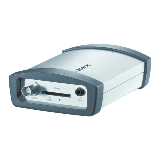
Line In: 9 kOhm typ., 5.5 Vp-p max. Line Out: 16 Ohm min., 3 Vp-p max. – Connect the camera to the socket VIDEO IN. – Use the LINE IN/OUT socket for audio line connections. F.01U.269.645 | V2 | 2012.06 Quick Installation Guide Bosch Sicherheitssysteme GmbH... -
Page 11: Creating A Serial Connection
If you require a serial connection to the VIP X1 XF E, connect the relevant cables to the terminal block. – Connect the terminal block to the orange socket on the VIP X1 XF E. Bosch Sicherheitssysteme GmbH Quick Installation Guide F.01U.269.645 | V2 | 2012.06... -
Page 12: Alarm And Relay Connections
Please observe the following specifications for the relay contact: max. 30 V (SELV), 200 mA – Connect the alarm switch to the appropriate terminals. – Connect the switch connection to the appropriate terminals. F.01U.269.645 | V2 | 2012.06 Quick Installation Guide Bosch Sicherheitssysteme GmbH... -
Page 13: Establishing The Network Connection
T X D G N D A C T E T H UTP Cat 5 RJ45 – Connect the VIP X1 XF E to the network via the ETH socket. Bosch Sicherheitssysteme GmbH Quick Installation Guide F.01U.269.645 | V2 | 2012.06... -
Page 14: Connecting The Power Supply
Connect the power supply unit to the 12V DC socket. The jack must fit a pin of 2 mm in diameter. – Insert the power supply unit plug into a suitable socket. F.01U.269.645 | V2 | 2012.06 Quick Installation Guide Bosch Sicherheitssysteme GmbH... -
Page 15: Assigning An Ip Address
When the unit is displayed in the list, Configuration Wizard starts automatically. If not, select Configuration Wizard... from the Tools menu. – Follow the instructions given in the Configuration Wizard window. Bosch Sicherheitssysteme GmbH Quick Installation Guide F.01U.269.645 | V2 | 2012.06... - Page 16 | Assigning an IP address VIP X1 XF E F.01U.269.645 | V2 | 2012.06 Quick Installation Guide Bosch Sicherheitssysteme GmbH...
- Page 18 Bosch Sicherheitssysteme GmbH Robert-Bosch-Ring 5 85630 Grasbrunn Germany www.boschsecurity.com © Bosch Sicherheitssysteme GmbH, 2012...
Need help?
Do you have a question about the VIP-X1XF-E and is the answer not in the manual?
Questions and answers