Maytag MFS 25 Installation And Maintenance Manual
Commercial washer
Hide thumbs
Also See for MFS 25:
- Installation instructions manual (16 pages) ,
- Programming manual (68 pages)

Related Manuals for Maytag MFS 25


Summary of Contents for Maytag MFS 25
- Page 1 MFS 25-35 INSTALLATION AND MAINTENANCE MANUAL SOFT MOUNTED WASHER EXTRACTOR PUBLICATION DATE : Sep 05 WITH ELECTRONIC PROGRAMMER 100646...
-
Page 2: Table Of Contents
1. TABLE OF CONTENTS Publication date : Sep 05 1. TABLE OF CONTENTS ....................1 2. WARNINGS ........................2 3. TECHNICAL INFORMATION ..................3 4. MACHINE INSTALLATION ................... 7 4.1. MACHINE INSPECTION........................7 4.2. MACHINE STORAGE.........................7 4.3. MACHINE POSITIONING ........................7 4.3.1. FREELY ON THE FLOOR......................8 4.3.2. -
Page 3: Warnings
2. WARNINGS FAILURE TO COMPLY WITH THE INSTRUCTIONS IN THIS MANUAL MAY LEAD TO INCORRECT USE OF THE WASHER EXTRACTOR, AND MAY RESULT IN BODILY INJURIES OR DEATH AND/OR DAMAGE TO THE LAUNDRY AND/OR THE WASHER EXTRACTOR. ♦ This English version is the original version. ♦... -
Page 4: Technical Information
3. TECHNICAL INFORMATION LOAD CAPACITY OF DRY 6 kg / 13 lb 7 kg / 16 lb 10 kg / 22 lb 16 kg / 36 lb LINEN (1/10) DIMENSIONS MACHINE DIMENSIONS Width 660 mm/25.98“ 660 mm/25.98“ 660 mm/25.98“ 835 mm/32.87“ Depth 770 mm/30.31“... - Page 5 Electric heating 9kW (400/440V 3AC) Electric heating 12kW (220-240V) Electric heating 12kW (400/440V 3AC) Electric heating 18kW (220-240V) Electric heating 18kW (400V 3AC) Electric heating 18kW (440V 3AC) Without el. heating (220-240C 1/3AC) WASHING FUNCTIONS Washing 48 RPM 48 RPM 48 RPM 45 RPM High extracting...
-
Page 6: Publication Date : Sep
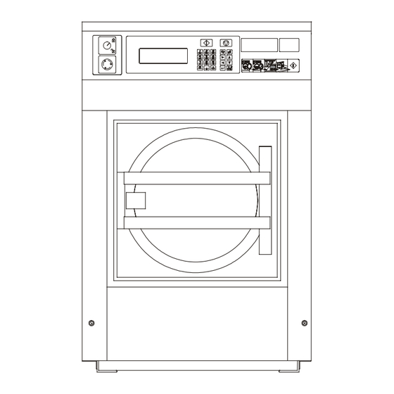
6kg / 13lb, 7kg / 16lb, 10kg / 22lb 16kg / 36lb machine with frequency control drive Fig. 3.1. 1. Control panel 8. Main switch 2. Connection liquid soap 9. Electrical supply connection 3. Serial plate 10. Drain 4. Soap hopper venting 11. - Page 7 6kg / 13lb 7kg / 16lb 10kg / 22lb 16kg / 36lb 660 mm / 25.98“ 660 mm / 25.98“ 660 mm / 25.98“ 835 mm / 32.87“ 685 mm / 26.97“ 685 mm / 26.97“ 785 mm / 30.91“ 960 mm / 37.8“...
-
Page 8: Machine Installation
4. MACHINE INSTALLATION 4.1. MACHINE INSPECTION When the machine is delivered, it is necessary to do a visual inspection for any damage that may have occurred during transit. If the package or pallet are damaged or signs of possible damage are evident, let the carrier note the condition on the shipping papers before the shipping receipt is signed. -
Page 9: Freely On The Floor
4.3.1. FREELY ON THE FLOOR The machine is to be located on a not elevated leveled concrete floor that comply with static and dynamic stress of the machine. The friction coefficient must be higher then 0,5 between the rubber feet and the floor material. Do not place the machine on a smooth surface but on a rough floor material like concrete. -
Page 10: Fixed On An Elevation
4.3.3. FIXED ON AN ELEVATION The machine can also be secured to a mounting base or foundation by means of bolts and anchoring bolts to assure the safety. When a concrete pad or a frame is used then is the maximum height 305 mm (12“). The pad or frame must be designed so that it can carry the static and dynamic forces. -
Page 11: Leveling The Machine
6kg / 13lb 7kg / 16lb 10kg / 22lb 16kg / 36lb 660 mm / 25.98“ 660 mm / 25.98“ 660 mm / 25.98“ 830 mm / 32.7“ 560 mm / 22.05“ 560 mm / 22.05“ 560 mm / 22.05“ 715 mm / 28.1“... - Page 12 After removing the shipping bars put the service panel, fig. 4.4. pos.3 and the rear panel, fig.4.4. pos.4 back on the machine. Keep the shipping bars pos.1, 2 for possible future transportation. Fig. 4.4. Transporting braces 100646 PUBLICATION DATE Sep 05 INSTALLATION AND MAINTENANCE MANUAL...
-
Page 13: Electrical Connection
4.5. ELECTRICAL CONNECTION 4.5.1. GENERAL WARNING ! THE MACHINE MUST BE CONNECTED TO THE POWER, GROUND, WATER, VENTILATION AND STEAM SUPPLY ACCORDING TO THE INSTALLATION MANUAL, IN COMPLIANCE WITH THE VALID LOCAL STANDARDS DONE BY QUALIFIED TECHNICIANS WITH PROPER AUTHORIZATION. THE VALID STANDARDS FOR CONNECTING TO THE LOCAL POWER NETWORK (TT / TN / IT, ...) MUST BE FOLLOWED. -
Page 14: Install Supply Cable To The Machine
Supply cable of the machine must have copper wires. The cross section of the supply wires depends on the supply voltage and on the total electrical power input of the machine (see table 4.3). The supply cable safety device against a short-circuit fault and overloading must be performed by automatic breakers or fuses in the laundry switchboard. -
Page 15: Checking Rotation Direction
4.5.5. CHECKING ROTATION DIRECTION CHECK IF THE DRUM ROTATES FROM THE FRONT VIEW IN CLOCKWISE DIRECTION DURING EXTRACTION. IF IT ROTATES IN OPPOSITE DIRECTION, DISCONNECT TWO PHASES OF THE CONNECTION FROM THE FREQUENCY INVERTER TO THE MOTOR , SWITCH THEM OVER AND CHECK AGAIN THE ROTATION DIRECTION. - Page 16 HOT WATER When the machine is provided with a hot water inlet, we advise connecting this inlet to a hot water supply that is set to 70°C / 158°F. The hot water supply needs to be large enough to provide the required hot water for the washers.
- Page 17 1. Waste channel cover 2. Drain elbow ∅76mm / 3“ 3. Clamp 4. Waste channel Without rubber feet : X1 = 55mm / 2.16" With rubber feet : X1 = 73mm / 2.87" X2 > 100mm / 3.93" X3 > 20mm / 0.78" Fig.
-
Page 18: Connection Of Liquid Washing Soaps Dosing
AIR VENT CONNECTION WARNING! WATCH OUT, VAPOURS ESCAPE FROM THE MACHINE THROUGH THE AIR VENT OPENING! DO NOT COVER OR CONNECT TO ANYTHING! On the backside, the washers are provided with an air vent opening of O.D. 75 mm / 3". Do not cover the washer air vent opening. -
Page 19: Preparing The Machine For Operation
1. Terminals for connection liquid soap pumps 2. Neutral line 3. Soap signals Fig. 4.7.B. Electrical connection soap pumps 4.8. PREPARING THE MACHINE FOR OPERATION CHECKING BEFORE PUTTING INTO SERVICE 1. Make sure the transporting braces are removed. 2. Put out all things from wash drum. 3. -
Page 20: Maintenance And Adjustments
5. MAINTENANCE AND ADJUSTMENTS WARNING ! ALWAYS FOLLOW SAFETY INSTRUCTIONS! DO NOT BYPASS ANY SAFETY DEVICES OR THEIR PARTS, ANY INTERFERENCE TO THE MACHINE FUNCTIONS AND CONSTRUCTION ARE PROHIBITED. BEFORE MAINTENANCE WORK DISCONNECT THE MACHINE POWER SUPPLY. USE THE PROPER CHEMICAL AGENTS WHICH AVOID CALCIUM SEDIMENTS ON HEATING ELEMENTS AND OTHER MACHINE PARTS. -
Page 21: Adjustments And Part´s Exchanges
5.2. ADJUSTMENTS AND PART´S EXCHANGES ADJUSTMENT OF DOOR SEAL THRUST MACHINES 6kg / 13lb, 7kg / 16lb, 10kg / 22lb If there is a water leakage around the door it is necessary to find out if the problem has been caused due to the door shift out of its position or if the door seal thrust should be adjusted. - Page 22 REPLACEMENT OF DOOR RUBBER MACHINES 6kg / 13lb, 7kg / 16lb, 10kg / 22lb 1. Open the door. Remove the door glass (Fig. 5.2.A, pos.3) with rubber (pos.2) from the stainless steel door (pos.5) by pushing it towards the drum. Do it carefully, do not damage the glass. 2.
- Page 23 REPLACEMENT / REGULATION OF THE BELT WARNING! MAKE SURE THE MACHINE IS DISCONNECTED FROM POWER SUPPLY BY PULLING OUT THE PLUG FROM THE SOCKET. On a new machine and after a belt replacement, make an inspection of the belt tightness : 10.
- Page 24 WATER FILTERS Machines are equipped with filters on water inlets. It is necessary to clean up the filters occasionally to avoid a prolongation of filling the machine with water. Intervals of cleaning depend on the quality of the water, for example foreign particles in the water line. WARNING ! BEFORE YOU START THE FILTER CLEANING CHECK IF THE INLET OF HOT WATER TO THE MACHINE IS CLOSED AND COLD.
-
Page 25: Troubleshooting Aids
6. TROUBLESHOOTING AIDS 6.1. ERROR HANDLING The timer allows the full control of the washing machine. When an error occurs then automatically the machine will go over to a safe state. With the diagnostic program you can determine the problem (See „Programming manual"). - Page 26 Problem Cause Solving the problem use the key switch at a distance less then 0,5 meter and in front of check the battery (the LED of the infrared key is eluminated when the button is pressed) • if the wrong machine type is •...
-
Page 27: Door Fails To Open
Problem Cause Solving the problem • change the shock absorbers shock absorbers are cold • a fault is occurred • wait until the counter has reached ‘0’ Door fails to open • power is off, safety is working • wait until safety device is inactive •... -
Page 28: List Of Recommended Spare Parts
7. LIST OF RECOMMENDED SPARE PARTS Find more detailed information in the spare part manual for individual machines. PRI 340 055 051 Drain valve 3“ 230V PRI 340 020 035 2-way water inlet valve PRI 340 030 038 3-way water inlet valve 273 112 994 945 Rubber for door glass, applicable for 16kg / 36lb PRI 505 000 045... -
Page 29: Putting The Machine Out Of Service
8. PUTTING THE MACHINE OUT OF SERVICE 8.1. DISCONNECTING THE MACHINE 1. Disconnect the outer electric power supply from the machine. 2. Switch off the main switch located on the back of the machine. 3. Turn off the outer water or steam inlet. 4. -
Page 30: Serial Number
IMPORTANT ! MACHINE TYPE: PROGRAMMER: - ELECTRONIC TIMER MCB EC - ELECTRONIC TIMER MCB FC INSTALLATION DATE: INSTALLATION CARRIED OUT BY: SERIAL NUMBER: ELECTRICAL DETAILS: .....VOLT....PHASE....HZ NOTE: ANY CONTACTS WITH YOUR DEALER REGARDING MACHINE SAFETY, OR SPARE PARTS, MUST INCLUDE THE ABOVE IDENTIFICATION.
Need help?
Do you have a question about the MFS 25 and is the answer not in the manual?
Questions and answers