Table of Contents
Advertisement
1. TABLE OF CONTENTS
1. TABLE OF CONTENTS ................................................................................................ 1
2. IMPORTANT SAFETY INSTRUCTIONS....................................................................... 2
3. TECHNICAL SPECIFICATIONS ................................................................................... 5
4. MACHINE INSTALLATION ........................................................................................... 9
4.1. MACHINE INSPECTION .........................................................................................................................9
4.2. WASHER STORAGE...............................................................................................................................9
4.3. WASHER POSITIONING.........................................................................................................................9
4.4. SHIPPING BRACKETS .........................................................................................................................12
4.5. ELECTRICAL CONNECTION................................................................................................................14
4.6. WATER CONNECTION.........................................................................................................................17
4.7. STEAM CONNECTION .........................................................................................................................19
4.8. WATER DRAIN CONNECTION ............................................................................................................19
4.9. AIR VENT CONNECTION .....................................................................................................................20
4.10. LIQUID SOAP CONNECTION.............................................................................................................20
4.11. PREPARING THE MACHINE FOR OPERATION...............................................................................23
5. MAINTENANCE AND ADJUSTMENTS ...................................................................... 24
5.1. MAINTENANCE.....................................................................................................................................24
5.2. ADJUSTMENTS AND PART´S EXCHANGES......................................................................................25
5.2.1. ADJUSTMENT OF DOOR SEAL THRUST ....................................................................................25
5.2.2. REPLACEMENT OF DOOR RUBBER ...........................................................................................26
5.2.3. ADJUSTING OF VIBRATION SWITCH ..........................................................................................26
5.2.4. REPLACEMENT / REGULATION OF THE BELT ..........................................................................27
5.2.5. WATER FILTERS............................................................................................................................28
5.2.6. TIGHTENING MOMENTS...............................................................................................................28
5.2.7. FUSES ............................................................................................................................................28
6. TROUBLESHOOTING AIDS ....................................................................................... 29
6.1. ERROR HANDLING ..............................................................................................................................29
6.2. PROBLEM CHECK LIST .......................................................................................................................29
6.3. DOOR FAILS TO OPEN ........................................................................................................................31
7. LIST OF RECOMMENDED SPARE PARTS ............................................................... 32
8. PUTTING THE MACHINE OUT OF SERVICE ............................................................ 33
8.1. DISCONNECTING THE MACHINE .......................................................................................................33
8.2. MACHINE LIQUIDATION ......................................................................................................................33
8.2.1. POSSIBILITY OF THE MACHINE LIQUIDATION BY THE SPECIALIZED COMPANY ........................33
8.2.2. POSSIBILITY OF THE MACHINE LIQUIDATION BY OWN POTENTIAL .....................................33
100646G MAYTAG PUB DATE 28 JUN 2007.DOC
INSTALLATION AND MAINTENANCE MANUAL
1
Advertisement
Table of Contents

Related Manuals for Maytag MFS18PDFTS


Summary of Contents for Maytag MFS18PDFTS
-
Page 1: Table Of Contents
8.1. DISCONNECTING THE MACHINE ...33 8.2. MACHINE LIQUIDATION ...33 8.2.1. POSSIBILITY OF THE MACHINE LIQUIDATION BY THE SPECIALIZED COMPANY ...33 8.2.2. POSSIBILITY OF THE MACHINE LIQUIDATION BY OWN POTENTIAL ...33 100646G MAYTAG PUB DATE 28 JUN 2007.DOC INSTALLATION AND MAINTENANCE MANUAL... -
Page 2: Important Safety Instructions
There are a lot of things that have influence on the temperature measurement. Therefore the temperature control of the washing bath is not very precise. INSTALLATION AND MAINTENANCE MANUAL 100646G MAYTAG PUB DATE 28 JUN 2007.DOC... - Page 3 Before starting inspection of frequency inverter, check for residual voltage across main circuit terminals + and -. This voltage must be below 30 VDC before you can access the inverter for inspection. 100646G MAYTAG PUB DATE 28 JUN 2007.DOC INSTALLATION AND MAINTENANCE MANUAL...
- Page 4 The emergency stop device takes care that at least the control circuit of the appliance is interrupted. INSTALLATION AND MAINTENANCE MANUAL 100646G MAYTAG PUB DATE 28 JUN 2007.DOC...
-
Page 5: Technical Specifications
El. heating 12kW (200-240V 3AC) El. heating 12kW (380-480V 3AC) El. heating 18kW (200-240V 3AC) El. heating 18kW (380-480V 3AC) 100646G MAYTAG PUB DATE 28 JUN 2007.DOC 6 kg / 13 lb 7 kg / 18 lb 10 kg / 25 lb 660 mm / 25.98“... - Page 6 730 N 16 Hz 16 Hz < 70 dB(A) < 70 dB(A) < 70 dB(A) Tab.3.A continuation 100646G MAYTAG PUB DATE 28 JUN 2007.DOC 48 RPM 45 RPM 980 RPM 0.1-0.8 MPa / 1-8 bar / 1-8 bar / 14.5-116 PSI 0.3-0.5 MPa /...
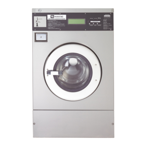
- Page 7 2. Connection liquid soap 3. Serial plate 4. Soap hopper venting 5. Water supply 6. Frequency inverter 7. Fuses 100646G MAYTAG PUB DATE 28 JUN 2007.DOC 16kg / 35lb Fig.3. 8. Main switch 9. Electrical supply connection 10. Drain 11. Adjustable leg 12.
- Page 8 68 mm / 2.67“ 850 mm / 33.46“ 339 mm / 13,34“ 874 mm / 34.40“ Tab.3.B 100646G MAYTAG PUB DATE 28 JUN 2007.DOC 16kg / 35lb 835 mm / 32.87“ 960 mm / 37.8“ 1295 mm / 50.98“ 715 mm / 28.15“...
-
Page 9: Machine Installation
- Take care that the floor where the machines will be placed is not combustible. 100646G MAYTAG PUB DATE 28 JUN 2007.DOC Fig.4.1. Serial plate INSTALLATION AND MAINTENANCE MANUAL... -
Page 10: Freely On The Floor
Distance A Distance B Distance C WARNING! NEVER APPLY THIS FOR A 16 kg / 35 lb MACHINE. INSTALLATION AND MAINTENANCE MANUAL 6kg / 13lb 7kg / 18lb 10kg / 25lb Tab.4.3.A Frame dimensions 100646G MAYTAG PUB DATE 28 JUN 2007.DOC... - Page 11 Do not tighten anchoring bolts before the concrete base around the bolts is completely secured. Tighten the anchoring bolts with the prescribed torque of the bolts. Fig.4.3.C Frame fixation dimensions 100646G MAYTAG PUB DATE 28 JUN 2007.DOC 1. Bolt M8 2. Securing nut 3.
-
Page 12: Leveling The Machine
565 mm / 22.24“ 130 mm / 5.12“ 130 mm / 5.12“ 115 mm / 4.53“ 115 mm / 4.53“ 100646G MAYTAG PUB DATE 28 JUN 2007.DOC 16kg / 35lb 830 mm / 32.7“ 715 mm / 28.1“ 57.5 mm / 2.26“... - Page 13 After removing the shipping brackets put the service panel, fig.4.4. pos.3 and the rear panel, fig.4.4. pos.4 back on the machine. Keep the shipping brackets pos.1, 2 for possible future transportation. Fig.4.4. Transporting brackets 100646G MAYTAG PUB DATE 28 JUN 2007.DOC INSTALLATION AND MAINTENANCE MANUAL...
-
Page 14: Electrical Connection
4. Washing machine 5. Phase conductors 6. Protective conductor 7. Main switch inlet terminal switchboard 8. Neutral conductor Fig.4.5.A Machine connection to electrical network (with a residual current device) INSTALLATION AND MAINTENANCE MANUAL 100646G MAYTAG PUB DATE 28 JUN 2007.DOC... -
Page 15: Supply Protection Device
(L3/W), (N), and the terminal (copper screw) marked with PE, see fig.4.5.C. – Provide a sag in the cable, in front of the cable strain relief. This will avoid ingress of condensed water into the machine, see fig.4.5.C. 100646G MAYTAG PUB DATE 28 JUN 2007.DOC INSTALLATION AND MAINTENANCE MANUAL... -
Page 16: Machine Protective Earth Connection And Equipotential Bonding
4 mm² (AWG 11) 6 mm² (AWG 9) 10 mm² (AWG 7) 16 mm² 25 mm² 35 mm² 100646G MAYTAG PUB DATE 28 JUN 2007.DOC Min. Protection conductor section in (AWG) 1,5 mm² (AWG 15) 2,5 mm² (AWG 13) 4 mm² (AWG 11) 6 mm²... -
Page 17: Water Connection
For best operation of the washer, water pressure must between 43 - 73 PSI (pound per square inch) or 0.3 - 0.5 MPa. Water pressure that is below minimum requirements can lengthen the wash cycle or/and not allow proper function of the washer. 100646G MAYTAG PUB DATE 28 JUN 2007.DOC INSTALLATION AND MAINTENANCE MANUAL... -
Page 18: Hot Water
118 l / 31.14 gal 20 l / 5.28 gal 138 l / 36.41 gal Tab.4.6.B Water consumption 100646G MAYTAG PUB DATE 28 JUN 2007.DOC Total 31 l / 8.18 gal 76 l / 20.05 gal 31 l / 8.18 gal... -
Page 19: Steam Connection
D2 = 100 mm / 4“ for two machines D3 = 125 mm / 5“ for three machines If the main drain cannot be sufficiently deodorized, install a deodorizer per machine. 100646G MAYTAG PUB DATE 28 JUN 2007.DOC INSTALLATION AND MAINTENANCE MANUAL... -
Page 20: Air Vent Connection
INSTALLATION AND MAINTENANCE MANUAL Depending of the number of liquid soap pumps 100646G MAYTAG PUB DATE 28 JUN 2007.DOC dispenser,... - Page 21 The liquid soap system may draw maximum 0,1A out the control circuit of the washer-extractor. 1. Terminals for connection liquid soap pumps 2. Neutral line 3. Soap signals Fig.4.10.C Electrical connection soap pumps 100646G MAYTAG PUB DATE 28 JUN 2007.DOC Fig.4.10.B Hose connection part INSTALLATION AND MAINTENANCE MANUAL...
- Page 22 Tighten the cable with the strain relief and close the box again with cover (pos.16). 4.11. FIG.4.10.E ELECTRICAL CONNECTION EXPLANATION INSTALLATION AND MAINTENANCE MANUAL Fig.4.10.D Rear panel (pos.16) (pos.18) (pos.17) by pulling (pos.17) back (pos.18) 100646G MAYTAG PUB DATE 28 JUN 2007.DOC...
-
Page 23: Preparing The Machine For Operation
10. Check the drum rotation direction during extracting according to the extracting label. 11. Check the vibration switch function during extracting (see also chapter „Adjustments and parts exchange“, adjustment of the vibration switch. 12. Check the emergency function. 100646G MAYTAG PUB DATE 28 JUN 2007.DOC INSTALLATION AND MAINTENANCE MANUAL... -
Page 24: Maintenance And Adjustments
– the external air relieves of the machine – check if ventilator in coolfins of inverter (if present) is functional – check if external ventilator (if present) is functional INSTALLATION AND MAINTENANCE MANUAL 100646G MAYTAG PUB DATE 28 JUN 2007.DOC... -
Page 25: Adjustments And Part´s Exchanges
5. Check if the door hinge has not moved, closing and opening of the door must be smooth. If the thrust adjusting has not been sufficient, exchange the door seal. 6. Hinge bolt 7. Hinge 8. Elimination washer 9. Door 100646G MAYTAG PUB DATE 28 JUN 2007.DOC Fig.5.2.1.B Door fastening INSTALLATION AND MAINTENANCE MANUAL... -
Page 26: Replacement Of Door Rubber
DO THIS CAREFULLY TO AVOID INJURIES BY VIBRATING AND FIRM PARTS OF THE MACHINE! AFTER YOU HAVE CHECKED THE FUNCTION, MOUNT THE MACHINE COVER BACK! 1. Microswitch 2. Limiter 3. Sensor INSTALLATION AND MAINTENANCE MANUAL Fig.5.2.3. Vibration switch 100646G MAYTAG PUB DATE 28 JUN 2007.DOC... -
Page 27: Replacement / Regulation Of The Belt
4. 2 x Screw M10 5. Motor pulley 6. Securing nut of bolt M16 (lower) 7. Securing nut of bolt M16 (upper) 8. Drum pulley 100646G MAYTAG PUB DATE 28 JUN 2007.DOC Fig.5.2.4. Regulation of belt INSTALLATION AND MAINTENANCE MANUAL... -
Page 28: Water Filters
The internal fuses FU1, FU2 for controlling circuits have value 1A (230V or 400V) and dimension L=32 mm / 1.26“ = 6,3 mm / 0.24“. The fuses are accessible from the machine rear, fig.3., pos.7. INSTALLATION AND MAINTENANCE MANUAL 100646G MAYTAG PUB DATE 28 JUN 2007.DOC... -
Page 29: Troubleshooting Aids
The dot to indicate that the software is in program mode can not be enabled or disabled 100646G MAYTAG PUB DATE 28 JUN 2007.DOC Cause no external power verify the external tension of the... - Page 30 100646G MAYTAG PUB DATE 28 JUN 2007.DOC Solving the problem...
-
Page 31: Door Fails To Open
4. If a light click is heard, the lock went to open position 5. Open the door if all safety conditions are fulfilled 6. Put the service panel back on his place and secure it again 100646G MAYTAG PUB DATE 28 JUN 2007.DOC Cause the suspension is damaged, the... -
Page 32: List Of Recommended Spare Parts
Electronic Controller MCB EC 516 696 Electronic Controller MCB FC 516 697 Electronic Controller MCG EC 516 698 Electronic Controller MCG FC 516814 9-Pole connector for liquid soap supply INSTALLATION AND MAINTENANCE MANUAL 100646G MAYTAG PUB DATE 28 JUN 2007.DOC... -
Page 33: Putting The Machine Out Of Service
6. Rubber ... waste group 191204 7. Metal... waste group 160117 8. Hubs with bearings ... waste group 170410 Offer the sorted waste to the company which is competent for further treatment. REMARKS: 100646G MAYTAG PUB DATE 28 JUN 2007.DOC INSTALLATION AND MAINTENANCE MANUAL... -
Page 35: Electrical Details
IMPORTANT ! MACHINE TYPE: PROGRAMMER: - ELECTRONIC TIMER MCB EC - ELECTRONIC TIMER MCB FC - ELECTRONIC TIMER MCG FC INSTALLATION DATE: INSTALLATION CARRIED OUT BY: SERIAL NUMBER: ELECTRICAL DETAILS: ...VOLT...PHASE...HZ NOTE: ANY CONTACTS WITH YOUR DEALER REGARDING MACHINE SAFETY, OR SPARE PARTS, MUST INCLUDE THE ABOVE IDENTIFICATION. -
Page 36: Publication Date: 28 Jun
MFS 18-25-35 INSTALLATION AND MAINTENANCE MANUAL SOFT MOUNTED WASHER EXTRACTOR PUBLICATION DATE: 28 Jun 2007 WITH ELECTRONIC PROGRAMMER 100646 G...
Need help?
Do you have a question about the MFS18PDFTS and is the answer not in the manual?
Questions and answers