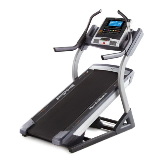
NordicTrack INCLINE TRAINER X7i User Manual
Ntl15010.1
Hide thumbs
Also See for INCLINE TRAINER X7i:
- User manual (42 pages) ,
- Manual (42 pages) ,
- User manual (38 pages)
Table of Contents
Advertisement
www.nordictrack.com
Model No. NTL15010.1
Serial No.
Write the serial number in the space
above for reference.
QUESTIONS?
If you have questions, or if parts
are damaged or missing, DO NOT
CONTACT THE STORE; please
contact Customer Care.
IMPORTANT: Please register this
product (see the limited warranty
on the back cover of this manual)
before contacting Customer Care.
CALL TOLL-FREE:
1-800-TO-BE-FIT
(1-800-862-3348)
Mon.–Fri. 6 a.m.–6 p.m. MT
Sat. 8 a.m.–4 p.m. MT
ON THE WEB:
www.nordictrackservice.com
CAUTION
Read all precautions and instruc-
tions in this manual before using
this equipment. Keep this manual
for future reference.
Serial
Number
Decal
USER'S MANUAL
Advertisement
Table of Contents

Related Manuals for NordicTrack INCLINE TRAINER X7i


Summary of Contents for NordicTrack INCLINE TRAINER X7i
- Page 1 USER’S MANUAL Model No. NTL15010.1 Serial No. Write the serial number in the space above for reference. Serial Number Decal QUESTIONS? If you have questions, or if parts are damaged or missing, DO NOT CONTACT THE STORE; please contact Customer Care.
-
Page 2: Table Of Contents
Apply the decal in the location shown. Note: The decals may not be shown at actual size. NORDICTRACK is a registered trademark of ICON IP, Inc. 271317... -
Page 3: Important Precautions
13. To purchase a surge suppressor, see your local 4. Keep the incline trainer indoors, away from NORDICTRACK dealer, call the telephone moisture and dust. Do not put the incline number on the front cover of this manual, or trainer in a garage or covered patio, or near see your local electronics store. - Page 4 19. The heart rate monitor is not a medical 23. Inspect and properly tighten all parts of the device. Various factors, including the user’s incline trainer regularly. movement, may affect the accuracy of heart DANGER: rate readings. The heart rate monitor is Always unplug the power intended only as an exercise aid in determin- cord immediately after use, before cleaning...
-
Page 5: Before You Begin
INCLINE TRAINER X7i manual. To help us assist you, note the product model ® INTERACTIVE. The INCLINE TRAINER X7i number and serial number before contacting us. The INTERACTIVE offers a selection of features designed model number and the location of the serial number to make your workouts at home more enjoyable and decal are shown on the front cover of this manual. -
Page 6: Part Identification Chart
PART IDENTIFICATION CHART Use the drawings below to identify small parts used for assembly. The number in parentheses below each draw- ing is the key number of the part, from the PART LIST near the end of this manual. The number following the key number is the quantity used for assembly. -
Page 7: Assembly
ASSEMBLY • Assembly requires two persons. • To identify small parts, see page 6. • Place all parts in a cleared area and remove the • Assembly requires the following tools: packing materials. Do not dispose of the packing materials until you finish all assembly steps. • the included hex keys • The underside of the walking belt is coated with • one Phillips screwdriver... -
Page 8: Screw (17) With Three 3/8" Star Washers (8
2. Attach the Upright (77) to the Base (80) with two 3/8" x 5 1/2" Screws (5) and a 3/8" x 2 3/4" Screw (17) with three 3/8" Star Washers (8) as shown. Start all three Screws, and then tighten them. Be careful not to pinch the Upright Wire (not shown) in the Upright. - Page 9 4. Have a second person hold the console assem- bly near the Uprights (77). Insert the console wire and the “R” pulse wire from the console assembly through the indicated tie. Connect the Upright Wire (78) to the console wire. See the inset drawing. The connectors should slide together easily and snap into place.
- Page 10 6. Tighten two #8 x 3/4" Screws (1) into the Console Base (87). Do not overtighten the Screws. Identify the Right Handrail Assembly (93). Hold the Right Handrail Assembly near the right Upright (77). Insert the pulse wire from the Right Handrail Assembly into the hole in the top of the Upright and pull it out of the end of the Upright.
- Page 11 8. Hold the Left Handrail Assembly (86) near the left Upright (77). Insert the pulse wire from the left handrail assembly into the hole in the top of the Upright and pull it out of the end of the Upright. Set the Left Handrail Assembly (86) onto the left Upright (77).
- Page 12 10. See page 13 and plug in the power cord. Next, see page 15 and turn on the power. Then, touch the 1 Step Incline button numbered 40 on the console. The Frame (58) will adjust to an incline of 40 percent. Then, turn off the incline trainer and unplug the power cord.
-
Page 13: Operation And Adjustment
OPERATION AND ADJUSTMENT HOW TO CONNECT THE POWER CORD nominal 120-volt circuit capable of carrying 15 or more amps. To avoid overloading the circuit, do Use a Surge Suppressor not plug other electrical devices, except for low- power devices such as cell phone chargers, into Your incline trainer, like other electronic equipment, the surge suppressor or into an outlet on the same circuit. - Page 14 CONSOLE DIAGRAM FEATURES OF THE CONSOLE You can even listen to your favorite workout music or audio books with the console’s premium stereo sound The incline trainer console offers an impressive array system while you get in shape. of features designed to make your workouts more To turn on the power and set up the console, see effective and enjoyable.
- Page 15 HOW TO TURN ON THE POWER HOW TO SET UP THE CONSOLE IMPORTANT: If the incline trainer has been Before using the incline trainer for the first time, set up exposed to cold temperatures, allow it to warm to the console. room temperature before you turn on the power.
- Page 16 HOW TO USE THE MANUAL MODE • T he elapsed time 1. Insert the key into the console. • T he distance that you have walked or run See HOW TO TURN ON THE POWER at the left. • The workout intensity bar 2. Select the manual mode. • T he approximate number of calories you have burned If the manual mode is not selected, press the...
- Page 17 Press the Home button to return to the default in the calorie display will appear; next, one or two menu (see HOW TO CHANGE CONSOLE dashes will appear; and then your heart rate will be SETTINGS on page 20 to set the default menu). If shown.
- Page 18 HOW TO USE AN ONBOARD WORKOUT The workout will continue in this way until the last segment of the profile flashes in the display and the 1. Insert the key into the console. last segment ends. The walking belt will then slow to a stop. See HOW TO TURN ON THE POWER on page 15. Note: The calorie goal is an estimate of the 2.
- Page 19 HOW TO USE AN IFIT LIVE WORKOUT During some workouts, the voice of a personal trainer will guide you through your workout. Note: To use an iFit Live workout, you must have access to a wireless network including an 802.11b, g, To stop the workout at any time, press the Stop or n router with SSID broadcast enabled (hidden net- button. The time will begin to flash in the display.
- Page 20 HOW TO CHANGE CONSOLE SETTINGS Default Menu—The default menu will appear when you insert the key into the console or when you The console features a settings mode that allows you press the Home button. Press the Enter button to view usage information, to personalize console set- repeatedly to select the manual main screen or the tings, and to set up and manage a wireless network iFit Live screen as the default menu.
- Page 21 Clear WiFi Setting—To erase the console’s Log in to your iFit Live account on the web page. wireless network settings and have it forget the Then, enter the numerical code into the indicated currently selected wireless network, follow the field. Follow any other instructions on the web instructions in the matrix.
- Page 22 6. Use WiFi–Advanced to set up a wireless HOW TO USE THE STEREO SOUND SYSTEM connection. To play music or audio books through the console’s This option will allow you to set up a wireless stereo speakers, you must connect your MP3 player, network connection using your computer, smart CD player, or other personal audio player to the con- phone, tablet, or other Wi-Fi device.
-
Page 23: How To Move The Incline Trainer
HOW TO MOVE THE INCLINE TRAINER Before moving the incline trainer, insert the key into the console, raise the incline to the maximum incline level, Console remove the key, and unplug the power cord. Due to the size and weight of the incline trainer, moving Belly it requires two or three persons. -
Page 24: Troubleshooting
TROUBLESHOOTING Most incline trainer problems can be solved by fol- c. Remove the key from the console, and then lowing the simple steps below. Find the symptom reinsert it. that applies, and follow the steps listed. If further assistance is needed, see the front cover of this d. - Page 25 Locate the Reed Switch (55) and the Magnet (41) b. If the walking belt is overtightened, incline trainer on the left side of the Pulley (42). Turn the Pulley performance may decrease and the walking belt until the Magnet is aligned with the Reed Switch. may become damaged.
- Page 26 SYMPTOM: The walking belt is off-center or slips SYMPTOM: The incline trainer will not connect to when walked on the wireless network a. If the walking belt is off-center, first adjust a. Make sure that you have followed all instructions the incline to 40 percent.
-
Page 27: Exercise Guidelines
EXERCISE GUIDELINES Burning Fat—To burn fat effectively, you must exer- WARNING: cise at a low intensity level for a sustained period of Before beginning this time. During the first few minutes of exercise, your or any exercise program, consult your physi- body uses carbohydrate calories for energy. - Page 28 SUGGESTED STRETCHES The correct form for several basic stretches is shown at the right. Move slowly as you stretch —never bounce. 1. Toe Touch Stretch Stand with your knees bent slightly and slowly bend forward from your hips. Allow your back and shoulders to relax as you reach down toward your toes as far as possible.
-
Page 29: Part List
PART LIST Model No. NTL15010.1 R0612A Key No. Qty. Description Key No. Qty. Description #8 x 3/4" Screw Grommet #8 x 3/4" Tek Screw Belly Pan Cover Left Inside Cover Power Switch 5/16" x 2 1/2" Screw Belly Pan 3/8" x 5 1/2" Screw Reed Switch 3/8"... - Page 30 Key No. Qty. Description Key No. Qty. Description Console Crossbar 3/8" x 2 1/2" Screw #8 x 1" Screw 1/4" Nut Crossbar – User’s Manual Console Clamp Note: Specifications are subject to change without notice. For information about ordering replacement parts, see the back cover of this manual.
-
Page 31: Exploded Drawing
EXPLODED DRAWING A Model No. NTL15010.1 R0612A... - Page 32 EXPLODED DRAWING B Model No. NTL15010.1 R0612A...
- Page 33 EXPLODED DRAWING C Model No. NTL15010.1 R0612A...
- Page 34 EXPLODED DRAWING D Model No. NTL15010.1 R0612A...
- Page 35 EXPLODED DRAWING E Model No. NTL15010.1 R0612A...
-
Page 36: Ordering Replacement Parts
ORDERING REPLACEMENT PARTS To order replacement parts, please see the front cover of this manual. To help us assist you, be prepared to provide the following information when contacting us: • the model number and serial number of the product (see the front cover of this manual) • the name of the product (see the front cover of this manual) • t he key number and description of the replacement part(s) (see the PART LIST and the EXPLODED DRAWING near the end of this manual) LIMITED WARRANTY IMPORTANT: You must register this product within 30 days of the purchase date to avoid added fees for service needed under warranty.
Need help?
Do you have a question about the INCLINE TRAINER X7i and is the answer not in the manual?
Questions and answers