Table of Contents
Advertisement
www.nordJctrack.com
Model No. NTL19910.0
Serial No.
Write the serial number in the space
above for reference.
QUESTIONS?
If you have questions, or if parts are
damaged or missing, DO NOT
CONTACT THE STORE; please
contact Customer Care.
iMPORTANT: Please register this
product (see the limited warranty
on the back cover of this manual)
before contacting
Customer Care.
CALL TOLL-FREE:
1-800-TO-BE-FIT
(1-800-862-3348)
Mon.-Fri.
6 a.m.-6
p.m. MT
Sat. 8 a.m.-4
p.m. MT
ON THE WEB:
www.nordictrackservice.com
USER'S
A
®
UAL
Advertisement
Table of Contents

Related Manuals for NordicTrack X7i incline trainer NTL19910.0


Summary of Contents for NordicTrack X7i incline trainer NTL19910.0
- Page 1 ® www.nordJctrack.com Model No. NTL19910.0 USER'S Serial No. Write the serial number in the space above for reference. QUESTIONS? If you have questions, or if parts are damaged or missing, DO NOT CONTACT THE STORE; please contact Customer Care. iMPORTANT: Please register this product (see the limited warranty on the back cover of this manual) before contacting...
- Page 2 Always wear athletic shoes T_lll • • Keep c,othing, ring ..hair I • Stop if you feel faint, dizzy, short breath..while operating treadmill. NordicTrack is a registered trademark of ICON IP, Inc.
- Page 3 Do not put the incline page 13. To purchase a surge suppressor, trainer in a garage or covered patio, or near your local NordicTrack dealer or call the tele= water. phone number on the front cover of this man- ual and order part number 146148, or see your local electronics store.
- Page 4 The incline trainer is capable of high speeds. Inspect and properly tighten all parts of the Adjust the speed in small increments to incline trainer regularly. avoid sudden jumps in speed. Never insert or drop any object into any 19. The pulse sensor is not a medical device. opening on the incline trainer.
- Page 5 BEFORE YOU BEGIN Thank you for selecting the revolutionary NordicTrack ® reading this manual, please see the front cover of this INCLINE TRAINER X71 INTERACTIVE. The INCLINE manual. To help us assist you, note the product model TRAINER X71 INTERACTIVE offers a selection of fea- number and serial number before contacting us.
-
Page 6: Assembly
ASSEMBLY Assembly requires two persons. Set the incline trainer in a cleared area and remove all packing materials, Do not dispose of the packing materials until assembly is completed. Note: The underside of the incline trainer walking belt is coated with high-performance lubricant, During shipping, some lubricant may be transferred to the top of the walking belt or the shipping carton, This is normal and does not affect incline trainer performance, if there is lubricant on top of the walking belt, simply wipe off the lubricant with a soft cloth and a mild, non-abrasive... - Page 7 Make sure that the power cord is unplugged. With the help of a second person, tip the incline trainer onto its left side. Have the second per- son hold the incline trainer to prevent it from tipping. Attach four Base Feet (10) and four Base Foot Spacers (11) to the Base (80) with four #8 x 1"...
- Page 8 Withthe helpofa second person, c arefully tip theincline trainer d ownso thattheBase(80)is flatonthefloor. Attach a Wheel ( 12)toeachsideof theBase (80)witha 3/8"x 2 1/2"Bolt(6)anda 3/8"Nut (7)(onlyonesideis shown). Set the Console Cover (87) face down on a soft surface. Remove the two #8 x 1 1/2" Screws (104) from the Console Back (89).
- Page 9 Position the Console Crossbar (103) between the Uprights (77, 79) as shown. Attach the Console Crossbar to the Uprights with four 5/16" x 2 3/4" Bolts (4) and four 5/16" Star Washers (9). Do not fully tighten the Bolts yet. Remove wire the tie from the Upright Wire (78).
- Page 10 Havea second person holdtheLeftPulse Handrail (86)neartheLeftUpright ( 77).Insert theLeftPulseWire(90)fromtheLeftPulse Handrail through theholeintheLeftUpright a nd pullit outof theholeinthesideoftheLeft Upright. Then,insert t heLeftPulse Wirethrough theloops in theties. Attach theLeftPulse Handrail (86)tothe Left Upright ( 77)withtwo3/8"x 5" Patch Bolts(34) andtwo3/8"StarWashers ( 8).Do not fully tighten the Patch Bolts yet.
- Page 11 Attach the Console (85) with four #8 x 3/4" Screws (1). Start all four Screws, and then tighten each of them. Do not overtighten Screws. Tighten the four loops around the wires by pulling on the ends of the ties. See step 5.
- Page 12 11. Press the Left and Right Accessory Trays (99, 100) into the Console Cover (87). Slide the two Handrail Covers (76) down against the Handrails (88). 12. Make sure that all parts are properly tightened before you use the incline trainer. Keep the included hex keys in a secure place.
- Page 13 OPERATION AND ADJUSTMENT THE PRE-LUBRICATED WALKING BELT that is properly installed and grounded in accor- dance with all local codes and ordinances. Your treadmill features a walking belt coated with high- IMPORTANT: The treadmill is not compatible with performance lubricant. IMPORTANT: Never apply sil- GFCl-equipped outlets.
- Page 14 CONSOLE DIAGRAM _NC_NE D_OINE TERRAIN SIMULATION WORKOUTS % GRAD£ _WARNING: STOP SPEED FEATURES OF THE CONSOLE You can also listen to your favorite workout music or audio books with the console's premium stereo sound The incline trainer console offers an impressive array system while you get in shape.
- Page 15 HOW TO TURN ON THE POWER HOW TO USE THE MANUAL MODE iMPORTANT: if the incline trainer has been ex- insert the key into the console. posed to cold temperatures, allow it to warm to See HOW TO TURN ON THE POWER at the left. room temperature before turning on the power, if...
- Page 16 If you press one of the numbered speed buttons, As you walk or run on the incline trainer, the the walking belt will gradually change speed until it screen can show the following workout information: reaches the selected speed setting. To select a speed setting that includes a decimal--such as 3.5 - The elapsed time...
- Page 17 To reset the console, press the iFit Menu button in To measure your heart rate, stand on the walking the upper right corner of the screen. To pause the platform and hold the metal contacts on the workout, press the Pause button. To continue the handrails for approximately ten seconds--avoid workout, press the Resume button or the Start but- moving your hands.
- Page 18 HOW TO USE A SET-A-GOAL WORKOUT ing belt will begin to move. Hold the handrails and begin walking. Insert the key into the console. The workout will function in the same way as the See step 1 on page 15. manual mode (see pages 15 to 17).
- Page 19 HOW TO USE A CALORIE BURN WORKOUT OR also show the distance of your workout and the AN ALL-TERRAIN TRAILS WORKOUT number of vertical feet you will climb. In addition, the screen will show a topographic map of the trail. Insert the key into the console.
- Page 20 workout. The actual number of calories that The workout will continue in this way until the last segment ends. The walking belt will then slow to a you burn will depend on your weight. In addi- stop. A workout summary will then appear on the tion, if you manually change the speed or in- screen.
- Page 21 HOW TO USE THE IFIT LIVE MODE Part 15 of the FCC Rules. These limits are designed to provide reasonable protection against harmful interfer- The iFit Live mode enables the incline trainer to com- ence in a residential installation. This equipment gen- municate with your wireless network.
- Page 22 HOW TO USE THE STEREO SOUND SYSTEM You must have your own wireless network and an 802.1 lb router with SSID broadcast enabled (hid- To play music or audio books through the console's den networks are not supported). speakers, you must connect your MP3 player, CD player, or other personal audio player to the console.
- Page 23 To use a static IP address, press the Use Static to the letter keyboard, press the ABC button. To IPs button. Enter the IP address, netmask, gate- capitalize a character, press the button with an up- way IP address, and at least one DNS. Press the ward-facing arrow.
- Page 24 HOW TO USE THE MAINTENANCE MODE Calibrate the screen. The console features a maintenance mode that allows If the screen is not properly calibrated, it will be dif- you to calibrate the incline and speed of the incline ficult to press the buttons on the screen. To cali- trainer, restore factory defaults, calibrate the screen, brate the screen, press the Calibrate Screen button update the console firmware, and view technical infor-...
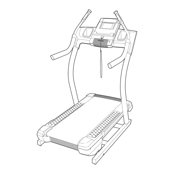
- Page 25 HOW TO MOVE THE iNCLiNE TRAINER Before moving the incline trainer, insert the key into the console, raise the incline to the maximum incline level, Console remove the key, and unplug the power cord. Due to the size and weight of the incline trainer, moving it requires two or three persons.
- Page 26 TROUBLESHOOTING Most incline trainer problems can be solved by following the steps below. Find the symptom that applies, and follow the steps listed, if further assistance is needed, please see the front cover of this manual. PROBLEM: The power does not turn on SOLUTION: a.
- Page 27 Locate the Reed Switch (55) and the Magnet (41) on the left side of the Pulley (42). Turn the Pulley until the View Magnet is aligned with the Reed Switch. Make sure that the gap between the Magnet and the Reed Switch is about 1/8 in.
- Page 28 PROBLEM: The walking belt is off-center or slips when walked on SOLUTION: a. If the walking belt is off-center, remove the key and UNPLUG THE POWER CORD. If the walking belt has shifted to the left, use the hex key to turn the left idler roller bolt clockwise 1/2 of a turn;...
- Page 29 EXERCISE GUiDELiNES Burning Fat--To burn fat effectively, you must exer- cise at a low intensity level for a sustained period of time, During the first few minutes of exercise, your body uses carbohydrate calories for energy. Only after the first few minutes of exercise does your body begin to use stored fat calories for energy, If your goal is to burn fat, adjust the intensity of your exercise until your heart rate is near the lowest number in your training...
- Page 30 PART LIST Model No. NTL19910.0 Rll10A To locate the parts listed below, see the EXPLODED DRAWING near the end of this manual. Key No. Qty. Description Key No. Qty. Description #8 x 3/4" Screw Grommet #8 x 1" Tek Screw Belly Pan Cover 5/16"x 1 3/8"...
- Page 31 Key No. Qty. Description Key No. Qty. Description Incline Sensor Wire PC Power Supply Right Pulse Handrail Frame Bushing Console Crossbar Rubber Spacer #8 x 1 1/2" Screw 5/16" Flat Washer Filter User's Manual Note: Specifications are subject to change without notice. For information about ordering replacement parts, see the back cover of this manual.
- Page 32 F" 43 _ "'"- 18---% 36---4 18 \ ¢.O ¢.O "'_-53 1____" 4_--1 3>...
- Page 33 r"" --72 © r..O r..O...
- Page 34 EXPLODED DRAWING Model No. NTL19910.0 Rll10A 4, 9 >_92 .'" ."'"107 <'-._. _--11 "'"-.. _--- _--2 [_";...
- Page 35 EXPLODED DRAWING Model No. NTL19910.0 Rll10A _100 19--...
- Page 36 ORDERING REPLACEMENT PARTS To order replacement parts, please see the front cover of this manual. To help us assist you, be prepared to provide the following information when contacting us: o the model number and serial number of the product (see the front cover of this manual) o the name of the product (see the front cover of this manual) o the key number and description of the replacement part(s) (see the PART LIST and the EXPLODED DRAWING near the end of this manual)
Need help?
Do you have a question about the X7i incline trainer NTL19910.0 and is the answer not in the manual?
Questions and answers