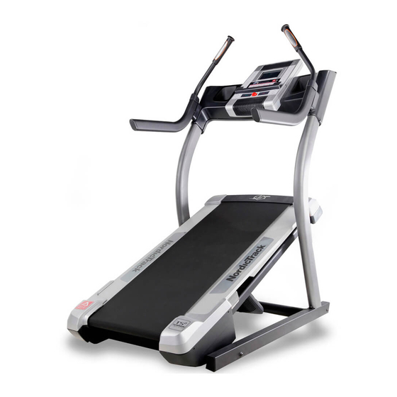
NordicTrack X7i Incline Trainer User Manual
Hide thumbs
Also See for X7i Incline Trainer:
- Manual (42 pages) ,
- User manual (42 pages) ,
- User manual (36 pages)
Table of Contents
Advertisement
Quick Links
Model No. NETL24810.0
Serial No.
USER'S MANUAL
Write the serial number in the space
above for reference.
Serial Number
Decal
QUESTIONS?
If you have questions, or if there are
missing parts, please contact us:
UK
Call: 08457 089 009
From Ireland: 053 92 36102
Website: www.iconsupport.eu
E-mail: csuk@iconeurope.com
Write:
ICON Health & Fitness, Ltd.
c/o HI Group PLC, Express Way
Whitwood, West Yorkshire
WF10 5QJ, UK
AUSTRALIA
Call: 1-800-237-173
E-mail:
australiacc@iconfitness.com
CAUTION
Read all precautions and instruc-
tions in this manual before using
this equipment. Save this manual
www.iconeurope.com
for future reference.
Advertisement
Table of Contents

Related Manuals for NordicTrack X7i Incline Trainer


Summary of Contents for NordicTrack X7i Incline Trainer
- Page 1 Model No. NETL24810.0 Serial No. USER'S MANUAL Write the serial number in the space above for reference. Serial Number Decal QUESTIONS? If you have questions, or if there are missing parts, please contact us: Call: 08457 089 009 From Ireland: 053 92 36102 Website: www.iconsupport.eu E-mail: csuk@iconeurope.com Write:...
-
Page 2: Table Of Contents
Apply the decal in the location shown. Note: The decals may not be shown at actual size. NORDICTRACK is a registered trademark of ICON IP, Inc. -
Page 3: Important Precautions
IMPORTANT PRECAUTIONS WARNING: To reduce the risk of serious injury, read all important precautions and in- structions in this manual and all warnings on your incline trainer before using your incline trainer. ICON assumes no responsibility for personal injury or property damage sustained by or through the use of this product. - Page 4 17. The incline trainer is capable of high speeds. 22. Inspect and properly tighten all parts of the Adjust the speed in small increments to incline trainer regularly. avoid sudden jumps in speed. 23. Never insert or drop any object into any 18.
-
Page 5: Before You Begin
BEFORE YOU BEGIN Thank you for selecting the revolutionary NORDIC- reading this manual, please see the front cover of this TRACK ® INCLINE TRAINER X7i INTERACTIVE. The manual. To help us assist you, note the product model INCLINE TRAINER X7i INTERACTIVE offers a selec- number and serial number before contacting us. -
Page 6: Part Identification Chart
PART IDENTIFICATION CHART Use the drawings below to identify small parts used for assembly. The number in parentheses below each draw- ing is the key number of the part, from the PART LIST near the end of this manual. The number following the key number is the quantity used for assembly. -
Page 7: Assembly
ASSEMBLY • Assembly requires two persons. • To identify small parts, see page 6. • Place all parts in a cleared area and remove the • Assembly requires the following tools: packing materials. Do not dispose of the packing materials until you finish all assembly steps. the included hex keys •... - Page 8 2. Identify the Right Upright (79), which is marked “Right.” Hold the Right Upright near the incline trainer. See the lower inset drawing. Tie the wire tie in the Right Upright (79) around the end of the Upright Wire (78). See the upper inset draw- Wire ing.
- Page 9 4. Set the Console Cover (87) face down on a soft surface. Remove the two #8 x 1 1/2" Screws (104) from the Console Back (89). The Screws will be used in another step. Separate the Console Back from the Console Cover (87), and remove the Console Crossbar (not shown) from inside.
- Page 10 6. Set the Console Cover (87) on the Uprights (77, 79). Make sure that the Console Cover is ori- ented so that the ties are toward the bottom. Attach the Console Cover (87) with the two #8 x 1 1/2" Screws (104) that you removed in step 4. Start both Screws, and then tighten them.
- Page 11 8. Have a second person hold the Console (85) near the Console Cover (87). Insert the wires from the Console through the indicated hole. Connect the Upright Wire (78), the Left and Right Pulse Wires (90, 91), and the Ground Hole Wire (97) to the wires extending from the Console (85).
- Page 12 10. Attach the Console Back (89) to the Console Cover (87) with two #8 x 1 1/2" Screws (104) and twelve #8 x 3/4" Screws (1). Start all four- teen Screws, and then tighten them. Do not overtighten the Screws. Make sure that no wires are pinched.
-
Page 13: Operation And Adjustment
OPERATION AND ADJUSTMENT HOW TO PLUG IN THE POWER CORD Follow the steps below to plug in the power cord. This product must be earthed. If it should malfunc- 1. Plug the indicated end of the power cord into the tion or break down, earthing provides a path of least socket on the treadmill. - Page 14 CONSOLE DIAGRAM Audio Jack FEATURES OF THE CONSOLE As you exercise, the console will display instant exer- cise feedback. You can also measure your heart rate The incline trainer console offers an impressive array using the handgrip heart rate monitor or the chest of features designed to make your workouts more ef- heart rate monitor.
- Page 15 HOW TO TURN ON THE POWER HOW TO USE THE TOUCH SCREEN IMPORTANT: If the incline trainer has been ex- The console features a tablet with a full-color touch posed to cold temperatures, allow it to warm to screen. The following information will help you become room temperature before you turn on the power.
- Page 16 HOW TO SET UP THE CONSOLE Next, enter a username and password and your e- mail address. Enter the activation code from the Before using the incline trainer for the first time, set up iFit Live flier that came with the incline trainer. the console.
- Page 17 HOW TO USE THE MANUAL MODE Note: The first time you adjust the incline, you must first calibrate the incline system (see step 4 on 1. Insert the key into the console. page 23). See HOW TO TURN ON THE POWER on page 5.
- Page 18 The displays at the top of the screen can show two 7. Turn on the fan if desired. types of information. Touch each display until the display shows the desired information. The fan features multiple speed settings and an auto mode. When the auto mode is selected, the If desired, adjust the volume by pressing the speed of the fan will automatically increase and de- Volume increase and decrease buttons on the...
- Page 19 HOW TO USE AN ONBOARD WORKOUT If the speed or incline setting is too high or too low at any time during the workout, you can override 1. Insert the key into the console. the setting by pressing the Speed or Elevation but- tons;...
- Page 20 HOW TO USE A SET-A-GOAL WORKOUT The workout will function in the same way as the manual mode (see pages 17 and 18). 1. Insert the key into the console. The workout will continue until you reach the goal See HOW TO TURN ON THE POWER on page that you set.
- Page 21 HOW TO USE AN IFIT LIVE WORKOUT Before some workouts will download, you must add them to your schedule on iFit.com. Note: To use an iFit Live workout, you must have ac- cess to a wireless network (see HOW TO USE THE For more information about the iFit Live work- WIRELESS NETWORK MODE on page 24).
- Page 22 HOW TO USE THE EQUIPMENT SETTINGS MODE position, and insert the key into the console. However, when you remove the key, the screen The equipment settings mode allows you to select a will show a demo presentation. language and the unit of measurement, to turn on and turn off the display demo mode, and to enable or dis- To turn on or turn off the display demo mode, first able the key.
- Page 23 HOW TO USE THE MAINTENANCE MODE The screen will show the progress of the update. When the update is complete, the incline trainer The maintenance mode allows you to update the con- will turn off and then turn back on. If it does not, sole firmware, calibrate the incline of the incline trainer, press the power switch into the off position.
- Page 24 HOW TO USE THE WIRELESS NETWORK MODE An information box will ask if you want to connect to the wireless network. Touch the Connect button The console features a wireless network mode that al- to connect to the network or touch the Cancel but- lows you to set up a wireless network connection.
- Page 25 HOW TO USE THE STEREO SOUND SYSTEM HOW TO USE THE INTERNET BROWSER To play music or audio books through the consoleʼs Note: To use the browser, you must have your own speakers, you must connect your MP3 player, CD wireless network and an 802.11b/n router with SSID player, or other personal audio player to the console.
-
Page 26: Troubleshooting
TROUBLESHOOTING Most incline trainer problems can be solved by fol- SYMPTOM: The console displays remain lit when lowing the simple steps below. Find the symptom you remove the key from the console that applies, and follow the steps listed. If further assistance is needed, see the front cover of this a. - Page 27 Locate the Reed Switch (55) and the Magnet (41) b. If the walking belt is overtightened, incline trainer on the left side of the Pulley (42). Turn the Pulley performance may decrease and the walking belt until the Magnet is aligned with the Reed Switch. may become damaged.
-
Page 28: How To Move The Incline Trainer
SYMPTOM: The walking belt is off-center or slips b. If the walking belt slips when walked on, first re- when walked on move the key and UNPLUG THE POWER CORD. Using the hex key, turn both idler roller screws a. If the walking belt is off-center, first remove the clockwise, 1/4 of a turn. -
Page 29: Exercise Guidelines
EXERCISE GUIDELINES Burning Fat—To burn fat effectively, you must exer- WARNING: cise at a low intensity level for a sustained period of Before beginning any time. During the first few minutes of exercise, your exercise program, consult your physician. body uses carbohydrate calories for energy. Only after This is especially important for persons over the first few minutes of exercise does your body begin age 35 or persons with pre-existing health... -
Page 30: Part List
PART LIST Model No. NETL24810.0 R0212A Key No. Qty. Description Key No. Qty. Description #8 x 3/4" Screw Grommet #8 x 1" Tek Screw Belly Pan Cover 5/16" Flat Washer Power Switch 5/16" x 2 3/4" Screw Belly Pan 3/8" x 3 1/2" Screw Reed Switch 3/8"... - Page 31 Key No. Qty. Description Key No. Qty. Description Incline Sensor Wire Filter Rubber Spacer UK Power Cord Console Crossbar Frame Bushing #8 x 1 1/2" Screw – Userʼs Manual Note: Specifications are subject to change without notice. For information about ordering replacement parts, see the back cover of this manual.
-
Page 32: Exploded Drawing
EXPLODED DRAWING A Model No. NETL24810.0 R0212A... - Page 33 EXPLODED DRAWING B Model No. NETL24810.0 R0212A...
- Page 34 EXPLODED DRAWING C Model No. NETL24810.0 R0212A...
- Page 35 EXPLODED DRAWING D Model No. NETL24810.0 R0212A...
-
Page 36: Ordering Replacement Parts
ORDERING REPLACEMENT PARTS To order replacement parts, please see the front cover of this manual. To help us assist you, be prepared to provide the following information when contacting us: • the model number and serial number of the product (see the front cover of this manual) •...
Need help?
Do you have a question about the X7i Incline Trainer and is the answer not in the manual?
Questions and answers