Table of Contents
Advertisement
®
NETWORK SERVICES
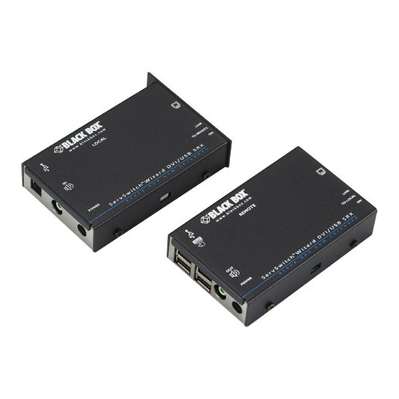
ServSwitch Wizard DVI/USB SRX
Extend one or two* quality DVI video links plus
four USB devices up to nearly 200 feet (60m) from
your computer.
Uses one or two* lengths of Category 5e, 6 or 7 twisted-pair cable.
* Dual-variant models
Order toll-free in the U.S.: Call 877-877-BBOX (outside U.S. call 724-746-5500)
Customer
FREE technical support 24 hours a day, 7 days a week: Call 724-746-5500 or fax 724-746-0746
Support
Mailing address: Black Box Corporation, 1000 Park Drive, Lawrence, PA 15055-1018
Information
Web site: www.blackbox.com • E-mail: info@ blackbox.com
®
ACU5501A-R4 ACU5501A-R3 ACU5501A-R2 ACU5502A-R3 ACU5502A-R2
™
Advertisement
Table of Contents


Need help?
Do you have a question about the ServSwitch ACU5501A-R4 and is the answer not in the manual?
Questions and answers