Epson TM-H5000II series Operator's Manual
Hybrid printer
Hide thumbs
Also See for TM-H5000II series:
- Manual (239 pages) ,
- User manual (88 pages) ,
- Development manual (24 pages)
Table of Contents
Advertisement
Quick Links
Using this online operator's guide
The words on the left side of this screen are bookmarks for all the
topics in this guide.
Use the scroll bar next to the bookmarks to find any topic you
want. Click a bookmark to instantly jump to its topic. (If you wish,
you can increase the size of the bookmark area by dragging the
dividing bar to the right.)
Use the scroll bar on the right side of this screen to move through
the text.
Use the zoom tools to magnify or reduce the page display.
Click the Find button if you want to search for a particular term.
(However, using the bookmarks is usually quicker.)
Complete online documentation for Acrobat Reader is located in the Help directory for Acrobat Reader.
TM-H5000II series
Operator's Manual
Return to main menu
Advertisement
Table of Contents

Related Manuals for Epson TM-H5000II series


Summary of Contents for Epson TM-H5000II series
- Page 1 TM-H5000II series Operator’s Manual Using this online operator’s guide The words on the left side of this screen are bookmarks for all the topics in this guide. Use the scroll bar next to the bookmarks to find any topic you want.
- Page 2 TM-H5000II series Operator’s Manual MICR Option Included 400826500 Printed in Japan...
-
Page 3: Caution Labels
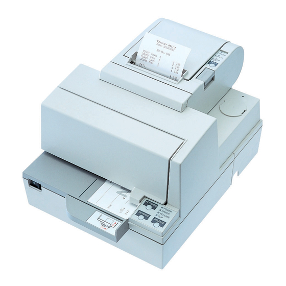
Printer Parts and Labels Paper roll cover Auto-cutter cover Paper roll control panel POWER ERROR Front cover PAPER FEED Slip paper control panel POWER FORWARD ERROR On/Off switch RELEASE SLIP REVERSE RELEASE Caution Labels CAUTION: Thermal head and printer head are hot. ATTENTION: La téte thermique et la téte d’imprimante sont chaudes. - Page 4 Instruction Labels Label affixed on the document table Ribbon installation label inside front cover Label inside paper Label inside roll cover cutter section CAUTION: Caution labels for drawer kick-out and display module connectors. Printerd in Japan...
-
Page 5: Quick Reference
Quick Reference This Quick Reference will direct you to key areas of this Operator’s Manual. For a complete listing of topics, see the Contents. Printer Parts and Labels inside front cover Ordering Paper and Ribbons page viii Where to order paper and ribbons. Setting Up the Printer page 1-1 How to set up the printer. - Page 6 Seiko Epson Corporation. No patent liability is assumed with respect to the use of the information contained herein. While every precaution has been taken in the preparation of this book, Seiko Epson Corporation assumes no responsibility for errors or omissions.
-
Page 7: Fcc Compliance Statement
FCC CLASS A FCC Compliance Statement For American Users This equipment has been tested and found to comply with the limits for a Class A digital device, pursuant to Part 15 of the FCC Rules. These limits are designed to provide reasonable protection against harmful interference when the equipment is operated in a commercial environment. -
Page 8: Declaration Of Conformity
DECLARATION OF CONFORMITY Product Name: Printer Model Name: M128C This printer conforms to the following Directives and Norms: Directive 89/336/EEC EN 55022 (1987 and 1994 2nd/1995) Class B EN 50082-1 (1992) IEC 801-2 (1991) IEC 801-3 (1984) IEC 801-4 (1988) Directive 90/384/EEC EN45501: (1992) -
Page 9: Emi And Safety Standards Applied
EMI and Safety Standards Applied The following standards are applied only to the printers that are so labeled. (EMC is tested using the EPSON PS-170 power supply) Europe: CE marking EN55022 EN50082-1 EN45501 Safety Standard: TÜV North America: EMI: FCC Class A... -
Page 10: About This Manual
Reference Chapter 4 contains specifications Appendix A tells how to change the DIP switch and paper near end settings, and Appendix B lists the EPSON Sales Subsidiaries and their addresses. Warnings, Cautions, and Notes WARNING: Warnings must be followed carefully to avoid serious bodily injury. -
Page 11: Slip Section
Ladder bar code printing is possible by using a bar code command. New paper handling enables easy paper roll loading. Both Receipt and Slip Standard EPSON customer display series connector (DM-D102-012/DM-D203- 012) (Available only for the serial interface model). Selectable receive buffer size (45 bytes or 4K bytes). -
Page 12: Options And Accessories
Options and Accessories Direct connection display modules, DM-D102-012 and DM-D203-012 (Available only for the serial interface model) EPSON power supply unit, PS-170 EPSON ribbon cassette, ERC-31(P) / ERC-31(B) Front extension table, WT-5000 MICR feed roller cleaning sheet (adhesive type) Part name:... - Page 13 Tel: (510) 782-0197 Fax: (510) 782-7124 In Europe: Nakagawa Mfg (Europe) GmbH. Krützpoort 16, 47804 Krefeld, Germany Tel: 02151-711051 Fax: 02151-713293 In Southeast Asia: N.A.K. Mfg (Malaysia) SDN BHD Lot 19-11, Bersatu Industrial Complexs, Jalan Satu, Kaw Per. Cheras Jaya,. Balakong Industrial Area, 43200 Cheras.
-
Page 14: Ordering Ribbon Cassettes
The TM-H5000II series printer uses a long-lasting ribbon cassette in the slip section. To order ribbon cassettes, contact your dealer or your local affiliate. See Appendix B for a list of EPSON subsidiaries with their addresses and telephone numbers. Introduction x... -
Page 15: Table Of Contents
Contents Quick Reference............i Introduction . - Page 16 Environmental Conditions ..........4-11 Appendix A DIP Switch and Paper Near End Settings Appendix B EPSON Sales Subsidiaries...
-
Page 17: Chapter 1 Setting Up The Printer
Chapter 1 Setting Up the Printer Unpacking Your printer box should include these items. If any items are damaged or missing, please contact your dealer for assistance. Ribbon Paper roll Hexagonal Switch lock screws cover These screws are used only for the serial interface (They are not always included.) See the note on page 1-4 for information about the hexagonal lock screws. -
Page 18: Removing The Protective Material
Removing the protective material 1. Open the printer by pulling up on the tab on the front cover. 2. Remove the two dampers from the printer as shown below. 3. Store the dampers with the other packing materials and use them when transporting your printer. -
Page 19: Connecting The Cables
Connecting the Cables and Grounding the Printer You can connect up to five cables to the printer. They all connect to the connector panel on the bottom of the printer, which is shown below: Grounding screw Power supply Drawer kick-out (See note below) Display module Interface... - Page 20 2. Tighten the screws on both sides of the cable connector. Note: Your printer has inch-type hexagonal lock screws installed. If your interface cable requires millimeter-type screws, replace the inch-type screws with the enclosed millimeter-type screws using a hex screwdriver (5 mm). Millimeter screw Inch screw 3.
- Page 21 Connecting the Drawer WARNING: Use a drawer that matches the printer specification. Using an improper drawer may damage the drawer as well as the printer. CAUTION: Do not connect a telephone line to the drawer kick-out connector; otherwise the printer and the telephone line may be damaged.
- Page 22 Anschließen der Lade WARNUNG: Eine für den Drucker geeignete Lade verwenden. Bei Verwendung einer falschen Lade kann diese oder der Drucker beschädigt werden. ACHTUNG: Kein Telefonkabel an die Schnappsteckerbuchse anschließen, da sonst der Drucker und die Telefonkabel beschädigt werden können. Das Kabel der Lade an die Schnappsteckerbuchse unten am anschlie Drucker neben dem Netßzanschluß...
- Page 23 Connecting the Display Module The display module connector of the printer can be used only for the serial interface. Plug the cable connector (provided with the direct connection display module) securely into the printer’s display module connector until it clicks. CAUTION: Be sure not to connect this cable to the drawer kick-out connector, which is to the left of the power supply...
- Page 24 Use the optional EPSON PS-170 or equivalent power supply for your printer. WARNING: Make sure that you use the EPSON PS-170 power supply or equivalent. Using an incorrect power supply may cause fire or electrical shock. 1-8 Setting Up the Printer...
- Page 25 CAUTIONS: When connecting or disconnecting the power supply from the printer, make sure that the power supply is not plugged into an electrical outlet. Otherwise you may damage the power supply or the printer. If the power supply’s rated voltage and your outlet’s voltage do not match, contact your dealer for assistance.
-
Page 26: Installing Or Replacing The Paper Roll
Installing or Replacing the Paper Roll Note: Be sure to use paper rolls that meet the specifications. Do not use paper rolls that have the paper glued to the core because the printer cannot detect the paper end correctly. 1. Make sure that the printer is not receiving data; otherwise, data may be lost. - Page 27 4. Insert the paper roll as shown. 5. Be sure to note the correct direction that the paper comes off the roll. Setting Up the Printer 1-11...
- Page 28 6. Pull out a small amount of paper, as shown. Then close the cover. 7. Tear off the paper as shown. 1-12 Setting Up the Printer...
-
Page 29: Installing The Ribbon Cassette
Installing the Ribbon Cassette Use the EPSON ERC-31(P) ribbon cassette for your printer. Note the label inside this section that can assist you in replacing the ribbon. CAUTION: Never turn the ribbon knob in the opposite direction of the arrow marked on the cassette; otherwise the ribbon cassette may be damaged. - Page 30 4. If you are replacing a used ribbon, grasp the end of the tab and remove it from the printer. See the illustration in step 5 for the location of the tab. 5. Turn the ribbon knob two or three times in the direction of the arrow to take up any slack in the ribbon.
-
Page 31: Using The Power Switch Cover
Using the Power Switch Cover WARNING: If an accident occurs when the power switch cover is attached, unplug the power supply cord from the outlet immediately. Continued usage may lead to fire or shock. You can use the enclosed power switch cover to make sure that the power switch is not accidentally pressed. -
Page 32: Running The Self Test With Slip Paper
2. While holding down the FEED button, turn on the printer using the switch on the front of the printer to begin the self test. The self test prints the printer settings and then prints the following, cuts the paper, and pauses. (The PAPER OUT light blinks.) Self test printing. -
Page 33: Adjustments And Settings
4. Remove the paper from the printer and feed another sheet of slip paper into the printer to print characters from the character table. Continue to feed slip paper into the printer until the self test prints the following: ***completed*** The printer is ready to receive data as soon as it completes the self test. -
Page 34: Chapter 2 Using The Printer
Chapter 2 Using the Printer Operating the Control Panels You can control the basic paper feeding operations of the printer with the buttons on the control panels. The indicator lights help you monitor the printer’s status. Paper Roll Control Panel POWER ERROR PAPER... -
Page 35: Indicator Lights
Buttons The printer and these buttons will not operate when the cover is open. Also these buttons can be disabled with the ESC c 5 command. FORWARD When the printer is in the slip mode (the SLIP light is on or blinking), press the FORWARD button once to advance slip paper one line. -
Page 36: Slip Paper Handling
Slip panel lights POWER The POWER light is on when the printer is on. ERROR This indicates an error in the slip section of the printer. See Chapter 3 for information on what to do when this light comes on. RELEASE This light indicates that platen and paper feed roller are released so that slip paper can be inserted. - Page 37 2. When the SLIP light blinks, insert the slip paper into the slip paper inlet using the right edge of the slip paper inlet as a guide. (Follow steps in the illustration.) Note: There is a label on the document table to assist you how to insert slip paper.
-
Page 38: Using The Micr Reader (Option)
Using the MICR Reader (Option) If your printer has the factory installed optional Magnetic Ink Character Recognition (MICR) reader that enables the printer to read and process MICR characters on personal checks, read this section. Reading MICR characters on personal checks To use the MICR function with personal checks, follow the steps below: CAUTION:... - Page 39 2. Turn the check over so that it is face down with the MICR characters on the right-hand side. The MICR characters must be next to the right edge of the paper inlet. 3. Insert the check straight into the paper inlet, using the right edge of the paper inlet as a guide.
-
Page 40: Chapter 3 Troubleshooting
Chapter 3 Troubleshooting Troubleshooting This chapter gives solutions to some printer problems you may have. General problems The lights on the control panel do not come on. Make sure that the power supply cables are correctly plugged into the printer, the power unit, and to the power outlet. Make sure that power is supplied to the power outlet. - Page 41 If there is no paper jam and the printer has been printing for quite a while, the print head may be overheated. If the print head is overheated, the printer will resume printing when the head has cooled (usually within two or three minutes). If there is no paper jam and the print head is not overheated, turn off the printer and turn it back on after about 10 seconds.
-
Page 42: Cleaning The Paper Roll Print Head
Paper roll printing is poor. Paper dust on the heating element of the thermal print head can lower the print quality. Try cleaning the print head as described below: Cleaning the paper roll print head CAUTIONS: After printing, the print head can be very hot. Be careful not to touch it. -
Page 43: Paper Handling Problems
A line of dots is missing in the printout. The print head may be damaged. Stop printing and contact your dealer or a qualified service person. Paper handling problems Paper is jammed inside the printer. CAUTIONS: Do not touch the print head because it can be very hot after printing continuously for a long time. - Page 44 3. If paper is caught in the automatic cutter in the receipt section and the paper roll cover cannot be opened, open the cutter cover as shown below. 4. Then turn the knob until you see in the opening, as shown in the illustration below.
-
Page 45: Auto Cutter Problems
Auto cutter problems The auto cutter is jammed. If a foreign object such as a push pin or paper clip drops in the auto cutter and causes the auto cutter to lock up, the printer enters an error state and begins the recovery operation automatically. If the problem is not serious, the auto cutter returns to its normal position without any intervention by the user. -
Page 46: Cleaning The Optional Micr Mechanism
2. Following the instructions on the label, rotate the knob until the appears in the hole. 3. Close the cutter cover. Cleaning the Optional MICR Mechanism MICR cleaning (when the printer is used with a MICR reader) Use a moistened cleaning sheet for the MICR head. Use an adhesive cleaning sheet for the MICR feed roller. - Page 47 Use the following or an equivalent commercially available cleaning sheet: PRESAT brand (KIC) "CHECK READER CLEANING CARD." Adhesive cleaning sheet A cleaning sheet is available from EPSON. Part name: Sheet-roller cleaning-A Part number: 1038046 Cleaning procedure You can perform cleaning either in self mode or command mode.
- Page 48 Self mode 1. Load paper roll into the printer. 2. Turn off the power. 3. Open the front cover. 4. Turn the power back on while holding down the RELEASE button. 5. Press the RELEASE button four times. 6. Close the front cover. 7.
-
Page 49: Hexadecimal Dump
9. Load the cleaning sheet like a standard check. If you are using the adhesive cleaning sheet, insert the printed (adhesive) side CAUTION: Be sure the printed (adhesive) side is up, and the sheet is inserted in the right direction. 10. - Page 50 4. Run any software program that sends data to the printer. The printer prints “Hexadecimal Dump” and then all the codes it receives in a two-column format. The first column contains the hexadecimal codes and the second column gives the ASCII characters that correspond to the codes.
-
Page 51: Chapter 4 Reference Information
Chapter 4 Reference Information Printing Specifications Slip Paper Printing method: Serial impact dot matrix Head wire 9-pin vertical line, 0.353 mm (1/72-inch) configuration: wire pitch Head wire diameter: 0.29 mm (.01") Printing direction: Bidirectional, minimum distance printing Number of characters: Alphanumeric characters: 95 International characters: 32 Extended graphics: 128 ×... -
Page 52: Receipt Paper
Receipt Paper Printing method: Thermal line printing 180 dpi × 180 dpi [the number of dots per Dot density: 25.4 mm (1”)] Printing direction: Unidirectional with friction feed 72 mm (2.83”), 512 dot positions Printing width: Characters per line: 42 (Font A) (default) 56 (Font B) Character spacing: 0.28 mm (.01”) (2 dots) (Font A)(default) - Page 53 Paper feeding speed: Approximately 120 mm/second (approximately 4.72”/second) continuous feeding Line spacing (default): 4.23 mm (1/6”) Programmable by control command. Number of characters: Alphanumeric characters: 95 International characters: 32 Extended graphics: 128 × 7 pages (including one space page) Font A: 12 × 24 (including 2-dot spacing Character structure: in horizontal) Font B: 9 ×...
-
Page 54: Ribbon Specifications
Recognition rating: Rating = ([total checks – number misread or not identified]/total checks) × 100 Check paper tested is EPSON standard check paper. Checks must be flat, without curls, folds, or wrinkles. The magnetic bias method is used for reading. -
Page 55: Paper Specifications
Paper Specifications Paper roll (single-ply): Size: Width: 79.5 mm ± 0.5 mm (3.13” ± 0.02”) Maximum 83 mm (3.27”) outside diameter: Paper roll Inside: 12 mm (0.47”) spool Outside: 18 mm (0.71”) diameter: Paper must not be pasted to the paper roll spool. Take up 80±... - Page 56 Normal paper (single-ply): 0.09 to 0.2 mm Copy capability and (.0035 to .0079”) paper thickness: Carbon copy paper combination: 5 sheets maximum (original + 4 copies) at 20° to 45°C (68° to 113°F) Backing paper: 0.06 to 0.15 mm (.0023 to .0059”) Copy and original: 0.04 to 0.07 mm (.0015 to .0028”) Carbon paper:...
- Page 57 Notes on slip paper The slip paper must be flat, without curls or wrinkles, especially at the top edges. Otherwise, the paper may rub against the ribbon and become dirty. There must be no glue on the bottom edge. Choose slip paper carefully since paper feeding and insertion are affected by gluing conditions (such as glue quality, method, and length) and glue location (see the illustration below).
-
Page 58: Reference Information
Since the TOF sensor uses a reflective photo sensor and it detects from the back of slip paper, do not use paper that has holes or dark portions with low reflection (less than 40% reflection) at the sensor position. Form stopper position MICR head 18.9 TOF sensor... -
Page 59: Electrical Characteristics
Electrical Characteristics +24 VDC ± 10% (optional power supply: EPSON Supply voltage: PS-170) Ripple 300mVpp or less (only when the voltage: printer is used with the MICR reader). Mean: approximately 1.9A Current (character font A α-N all columns Operating: consumption: (at... -
Page 60: Reliability
Reliability Slip: Life (when Mechanism: 12,000,000 lines printing alphanumeric characters): Print head: 200 million characters (when printing with font B) MICR reader 240,000 passes mechanism (only when the printer is used with the MICR reader): End of life is defined to have reached the end of its life when it reaches the... -
Page 61: Environmental Conditions
Receipt: Life: Mechanism: 15,000,000 lines Thermal head: 100 million pulses, 100 km Auto cutter: 1,500,000 cuts MTBF: 180,000 hours MCBF: 37,000,000 lines Environmental Conditions Temperature: Operating: 5° to 45°C (41° to 113°F) Storage: -10° to 50°C (14° to 122°F) (except for paper) Humidity: Operating: 10 to 90% RH... -
Page 62: Dip Switch And Paper Near End Settings
Appendix A Dip Switch and Paper Near End Settings Although the factory settings are best for almost all uses, if you have special requirements, you can change the DIP switch or paper near end settings. Setting the DIP Switches DIP switch functions Your printer has two sets of DIP switches. - Page 63 Transmission Speed Transmission Speed (BPS)-bits per second 2400 4800 9600 19200 Set 2 Function Handshaking (BUSY Off line or Receive buffer full condition) receive buffer full Customer display Connected Not connected (DM-D) connection Selects print density Refer to table below Reserved: do not change settings Fixed to OFF I/F pin 6 reset signal...
- Page 64 Notes: • When pin 6 of the interface connector is used for the reset signal, the printer is reset at MARK on the RS-232 level. • When pin 25 of the interface connector is used for the reset signal, the printer is reset at SPACE on the RS-232 level or at HIGH on the TTL level.
-
Page 65: Parallel Interface Specification
Parallel interface specification Set 1 Function Auto line feed Always enabled Always disabled Receive buffer capacity 45 bytes 4K bytes 1-3 ~ Undefined — — Set 2 Function •Off-line Handshaking (BUSY •Receive buffer full •Receive buffer full condition) •Reading data •Reading data Reserved Fixed to Off... - Page 66 Print Density and Low power consumption mode selection (Only for Receipt) Print Density SW 2-3 SW 2-4 Low power consumption mode 1 (Light) 3 (Dark) Notes: • When pin 6 of the interface connector is used for the reset signal, the printer is reset at MARK on the RS-232 level.
-
Page 67: Changing The Dip Switch Settings
Changing the DIP switch settings If you need to change settings, follow the steps below to make your changes: CAUTION: Turn off the printer while removing the DIP switch cover to prevent an electric short, which can damage the printer. 1. -
Page 68: Adjusting The Paper Near End Sensor
Adjusting the Paper Near End Sensor The paper near end sensor detects when paper is almost gone by measuring the diameter of the paper roll. The sensor has two settings. Because of variations in paper roll cores, it is not possible for the sensor to measure exactly the length of paper left on the roll when the sensor is triggered. -
Page 69: Epson Sales Subsidiaries
Appendix B Sales Subsidiaries EPSON EPSON AMERICA INC./OEM DIV. 20770 Madrona Ave. Torrance, CA 90559-2842 U.S.A. Tel : 1-310-787-6300 Fax : 1-310-782-5350 EPSON EUROPE B.V. Prof. J.H. Bavincklaan 5 1183 AT Amstelveen The Netherlands Tel : 31-(0)20-5475-251 Fax : 31-(0)20-6454-315 EPSON Deutschland GmbH Zülpicher Strasse 6, 40549... - Page 70 EPSON HONG KONG LIMITED 25/F., Harbor Centre, 25, Harbor Road, Wanchai, Hong Kong Tel : 852-2-585-4663 Fax : 852-2-827-4346 EPSON TAIWAN TECHNOLOGY 10f, No. 287, Nanking E. Road, Sec. 3 & TRADING LTD. Taipei, Taiwan R.O.C. Tel : 886-(0)2-717-7360 Fax : 886-(0)2-718-9366 SEIKO EPSON CORP.
Need help?
Do you have a question about the TM-H5000II series and is the answer not in the manual?
Questions and answers