
Related Manuals for Motorola SB5100 Series


Summary of Contents for Motorola SB5100 Series
- Page 1 ® S U R F b o a r d S B 5 1 0 0 S e r i e s C a b l e M o d e m I n s t a l l a t i o n M a n u a l b l e a r d ®...
- Page 2 CAUTION RISK OF ELECTRIC SHOCK CAUTION: TO REDUCE THE RISK OF ELECTRIC SHOCK, DO NOT REMOVE COVER (OR BACK). NO USER-SERVICEABLE PARTS INSIDE. REFER SERVICING TO QUALIFIED SERVICE PERSONNEL. Caution These servicing instructions are for use by qualified personnel only. To reduce the risk of electrical shock, do not perform any servicing other than that contained in the Installation and Troubleshooting Instructions unless you are qualified to do so.
- Page 3 According to 47CFR, Parts 2 and 15 for Class B Personal Computers and Peripherals; and/or CPU Boards and Power Supplies used with Class B Personal Computers, Motorola, Inc. Broadband Communications Sector, 101 Tournament Drive, Horsham, PA 19044, 1-215-323-1000, declares under sole responsibility that the product identifies with 47CFR Part 2 and 15 of the FCC Rules as a Class B digital device. Each product marketed is identical to the representative unit tested and found to be compliant with the standards.
- Page 4 Motorola, Inc. Motorola reserves the right to revise this publication and to make changes in content from time to time without obligation on the part of Motorola to provide notification of such revision or change. Motorola provides this guide without warranty of any kind, either implied or expressed, including, but not limited to, the implied warranties of merchantability and fitness for a particular purpose.
-
Page 5: Table Of Contents
Contents Section 1 Introduction Using This Manual....................................1-2 Document Conventions ...................................1-2 If You Need Help ....................................1-3 Calling for Repairs....................................1-3 Section 2 Overview Top and Front Panel..................................2-2 Rear Panel ......................................2-4 Section 3 Installation and Operation Before You Begin .....................................3-2 Installing a Single User ..................................3-3 Setting Up a USB Driver...................................3-5 Setting Up a USB Driver for Windows 98 ..........................3-5 Setting Up a USB Driver for Windows 2000 ........................3-10... - Page 6 Contents Recovering from Windows 98 or Win98_SE Installation Errors....................3-46 Remove Program................................... 3-46 Solutions ....................................3-47 Solution 1..................................3-47 Solution 2..................................3-48 Setting the Frequency Using StormWatch ..........................3-49 Section 4 HTML User Interface Section 5 Troubleshooting Appendix A Specifications Downstream......................................A-1 Upstream......................................A-1 General......................................A-1...
- Page 7 Contents SURFboard Cable Modem Specific Log Messages......................B-7 Baseline Privacy ................................B-7 DHCP / TFTP................................. B-10 Filtering ..................................B-13 Driver....................................B-19 Registration..................................B-20 Miscellaneous ................................B-21 Acquisition..................................B-22 Unit Update ..................................B-23 Figures Figure 2-1 SURFboard cable modem data path ...........................2-1 Figure 2-2 Front panel LEDs and Standby button........................2-2 Figure 2-3 Rear-panel connections and LEDs..........................2-3 Figure 3-1 Cable connections ................................3-3...
- Page 8 ® The Motorola SURFboard SB5100 series cable modem provides a link from a home or business computer to a high-speed DOCSIS or Euro-DOCSIS 2.0, 1.1, or 1.0 compliant data network. This network provides a downstream data transfer rate up to 38 Mbps in a single 6 MHz channel (55 Mbps in a 8 MHz channel for Euro-DOCSIS) using 64 QAM and 256 QAM technologies.
-
Page 9: Using This Manual
Introduction Using This Manual The following sections provide information and instructions to install, configure, and operate the SURFboard cable modem: Section 1 Introduction provides a product description, the technical help line, and repair/return information. Section 2 Overview describes the functions of the SURFboard cable modem and identifies the front-panel LEDs and the rear-panel connectors. -
Page 10: If You Need Help
24 hours per day, 7 days per week. Calling for Repairs If repair is necessary, call the Motorola BCS Repair Facility at 1-800-227-0450 for a Return for Service Authorization (RSA) number before sending the unit. The RSA number must be prominently displayed on all equipment cartons. -
Page 11: Overview
Section 2 Overview The SURFboard cable modem delivers digital multimedia content in a two-way transmission system. It provides access to a cable data network, which provides access to the Internet and World Wide Web. The SURFboard cable modem is authorized by a cable modem terminations system (CMTS) for use on the network and automatically configures itself with parameters received from the CMTS or headend. -
Page 12: Top And Front Panel
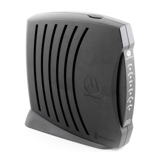
Overview The SURFboard cable modem provides an HTML user interface to: Monitor the cable modem and data signals Troubleshoot network connections Top and Front Panel The six front-panel LEDs provide status and activity information. The Standby button enables the subscriber to disconnect the Ethernet and USB interfaces from the cable modem network. The LEDs and Standby button are illustrated in Figure 2-2: Figure 2-2 Front panel LEDs and Standby button... - Page 13 Overview Item When Flashing When On Power Startup diagnostics in process. The cable modem is powered on. Receive Scanning for a receive (downstream) The downstream channel is connected. channel connection. Send Scanning for a send (upstream) channel The upstream channel is connected. connection.
-
Page 14: Rear Panel
Overview Rear Panel The SURFboard cable modem rear panel provides the cabling connectors, status LEDs, and power plug as illustrated in Figure 2-3: Figure 2-3 Rear-panel connections and LEDs +12VDC Table 2-2 describes the SURFboard cable modem rear-panel connections and LEDs: Table 2-2 Rear-panel connections and LEDs Item... -
Page 15: Installation And Operation
Section 3 Installation and Operation This section provides instructions for cabling all SURFboard cable modem models and checking their operation. To complete the installation, you must: Connect the cables Configure the subscriber’s computer Avoid damaging the SURFboard cable modem or your PC with static electricity. +12VDC To release any static charges, touch the... -
Page 16: Before You Begin
Installation and Operation Before You Begin Before you begin the installation, take a few minutes to review the installation information, gather the required items, and complete the tasks listed below to make the installation as quick and easy as possible: Verify that the following items are included with the SURFboard cable modem: Power adapter Connects the SURFboard cable modem to the AC electrical outlet... -
Page 17: Installing A Single User
Installation and Operation Installing a Single User You can connect a single user to a SURFboard cable modem using the USB or Ethernet port. Allow 5 to 30 minutes to power up the first time because the SURFboard cable modem must find and lock on the appropriate channels for communications. - Page 18 “Setting Up a USB Driver for Windows Me,” on page 3-14 “Setting Up a USB Driver for Windows XP,” on page 3-16 You can upgrade the USB drivers from the Internet. For information, check our website http://www.motorola.com/broadband. Ethernet: Connect the 10/100Base-T Ethernet cable to the SURFboard cable modem connector marked...
-
Page 19: Setting Up A Usb Driver
Installation and Operation Setting Up a USB Driver The following subsections provide instructions for setting up a USB driver for Windows 98, Windows 2000, Windows Me, and Windows XP. Setting Up a USB Driver for Windows 98 To set up a USB driver for Windows 98: Be sure the SURFboard Cable Modem CD-ROM is inserted in your CD-ROM drive before you plug in the USB cable. - Page 20 Installation and Operation Click Next and the following window is displayed: Ensure that the Search for the best driver for your device is selected as shown on the window above. Click Next, and the window below is displayed showing a location: Ensure that the CD-ROM drive is the only box checked as shown in the window above.
- Page 21 Installation and Operation If the computer does not locate the driver, the previous window is displayed again. Select Specify a location and type the location of your CD-ROM drive: In this example, to load the driver successfully, you may need to click Browse to manually select the NetMotCM.sys files on the CD-ROM.
- Page 22 Installation and Operation When the window below is displayed, click Next. If a window with the message Copying Files... displays and asks for your CD-ROM drive, type your CD-ROM drive letter (for example, “D:”) and click OK. If an Insert Disk window similar to the one below is displayed, Windows 98 system files are needed to complete the installation.
- Page 23 Installation and Operation After all the necessary files are loaded, the window below is displayed confirming a successful installation: Click Finish. The window below is displayed: Click Yes to restart your computer. When you have successfully finished setting up the USB driver, you can continue with “Configuring for TCP/IP in Windows 95, Windows 98, or Windows Me,”...
-
Page 24: Setting Up A Usb Driver For Windows 2000
3-10 Installation and Operation Setting Up a USB Driver for Windows 2000 To set up a USB driver for Windows 2000: Be sure the SURFboard Cable Modem CD-ROM is inserted in your CD-ROM drive before you plug in the USB cable. This CD contains the USB drivers and must be inserted and read by the PC before you connect the cable modem to the PC. - Page 25 Installation and Operation 3-11 Click Next, and the following window is displayed: Although your SURFboard cable modem model number may be different than in the images in this manual, the procedure is the same. Ensure that Search for a suitable driver for my device is selected. Click Next and the following window is displayed: Ensure that the box next to the CD-ROM drives is the only one checked as shown in the window above.
- Page 26 3-12 Installation and Operation Click Next and the window shown below is displayed: Although your SURFboard cable modem model number may be different than in the images in this manual, the procedure is the same Click Next. If the Insert Disk window is displayed, be sure the SURFboard Cable Modem CD-ROM is in the CD-ROM drive and follow steps 8 to 12.
- Page 27 Installation and Operation 3-13 Double-click the NetMotCM.sys file. The Files Needed window is displayed. Click OK. The Found New Hardware Wizard window is displayed: Click Finish to complete the installation. When you have successfully finished setting up the USB driver, you can continue with “Configuring for TCP/IP in Windows 2000,”...
-
Page 28: Setting Up A Usb Driver For Windows Me
3-14 Installation and Operation Setting Up a USB Driver for Windows Me To set up a USB driver for Windows Me: Be sure the SURFboard Cable Modem CD-ROM is inserted into the CD-ROM drive before you plug in the USB cable. This CD contains the USB drivers and must be inserted and read by the PC before you connect the cable modem to the PC. - Page 29 Installation and Operation 3-15 If the window below is displayed, click Finish: Otherwise, ensure that the SURFboard Cable Modem CD-ROM is correctly inserted in your CD-ROM drive. When you have successfully finished setting up the USB driver, you can continue with “Configuring for TCP/IP in Windows 95, Windows 98, and Windows Me,”...
-
Page 30: Setting Up A Usb Driver For Windows Xp
3-16 Installation and Operation Setting Up a USB Driver for Windows XP To set up a USB driver for Windows XP: Be sure the SURFboard Cable Modem CD-ROM is inserted into the CD-ROM drive before you plug in the USB cable. This CD contains the USB drivers and must be inserted and read by the PC before you connect the cable modem to the PC. -
Page 31: Configuring For Tcp/Ip In Windows Xp
Installation and Operation 3-17 Click Next. Windows XP automatically searches for the correct USB drivers and installs them. The following window is displayed: Click Finish to complete the installation. If you have difficulties setting up the USB driver, follow the instructions for “Removing the USB Driver from Windows XP on page 3-41. -
Page 32: Configuring The Computer For Tcp/Ip
3-18 Installation and Operation Configuring the Computer for TCP/IP The computer must be configured for TCP/IP. An IP address is assigned automatically during the TCP/IP configuration process. Instructions are provided for Windows 95, Windows 98, Windows Me, Windows 2000, and Window XP users. The SURFboard cable modem contains all required software. - Page 33 Installation and Operation 3-19 Select the adapter to be used for the SURFboard cable modem connection and then click Add. The Select Network Component Type window is displayed: Double-click the Protocol option. The Select Network Protocol window is displayed: Click Microsoft in the Manufacturers section and then click TCP/IP in the Network Protocols section.
- Page 34 3-20 Installation and Operation Click TCP/IP on the Network window. If there is more than one TCP/IP entry, choose the one for the Ethernet card or USB port connected to the cable modem. Click Properties. The TCP/IP Properties window is displayed: Click the IP Address tab.
-
Page 35: Configuring For Tcp/Ip In Windows 2000
Installation and Operation 3-21 Configuring for TCP/IP in Windows 2000 To configure for TCP/IP for Windows 2000: On the Windows Desktop, click Start. Click Settings and then Control Panel from the pop-up menus: Double-click the Network and Dial-up Connections icon on the Control Panel window to display the window shown below: On the Network and Dial-up Connections window, double-click Local Area Connection number. - Page 36 3-22 Installation and Operation The Local Area Connection number Status window is displayed: Click Properties. A window similar to the following is displayed: If Internet Protocol (TCP/IP) is displayed in the list of network components, TCP/IP is installed. You can skip to step 10. SURFboard Cable Modem Installation Manual...
- Page 37 Installation and Operation 3-23 If Internet Protocol (TCP/IP) is not in the list, click Install. The Select Network Component Type window is displayed: Click Protocol on the Select Network Component Type window and then click ADD. The Select Network Protocol window is displayed similar to the one shown below: Click Internet Protocol (TCP/IP) in the Network Protocol section of Select Network Protocol window.
- Page 38 3-24 Installation and Operation The Local Area Connection number Properties window is re-displayed: On the Local Area Connection number Properties window, ensure that the box next to Internet Protocol (TCP/IP) is checked. Click Properties. The Internet Protocol (TCP/IP) Properties window is displayed: Ensure that Obtain IP address automatically and Obtain DNS server address automatically are selected.
-
Page 39: Configuring For Tcp/Ip In Windows Xp
Installation and Operation 3-25 Click OK to accept the TCP/IP settings. Click OK to close the Local Area Connection number Properties window. Click OK when prompted to restart the computer and then click OK again. When you complete the TCP/IP configuration, go to “Verifying an IP Address in Windows 2000 or Windows XP”... - Page 40 3-26 Installation and Operation If a classic view similar to the illustration below is displayed, click Network Connections to display the LAN or High-speed Internet connections. Right-click on your network connection. If more than one connection is displayed, be sure to select the one for your network interface.
-
Page 41: Verifying An Ip Address
Installation and Operation 3-27 Verify that the settings are correct, as shown in the illustration below: Click OK to close the TCP/IP Properties window. Click OK to close the Local Area Connection Properties window. When you complete the TCP/IP configuration, go to “Verifying an IP Address in Windows 2000 and Windows XP on page 3-29 Verifying an IP Address The following sections describe how to verify an IP address. - Page 42 3-28 Installation and Operation Type winipcfg.exe and then click OK. The IP Configuration window is displayed: In Windows 98, IP Autoconfiguration should not be shown before IP address or an error condition exists. An example is shown below. The values shown for Adapter Address, IP Address, Subnet Mask, and Default Gateway on your PC will be different from those shown in the examples.
-
Page 43: Verifying An Ip Address In Windows 2000 And Windows Xp
Installation and Operation 3-29 Verifying an IP Address in Windows 2000 and Windows XP To check the IP address on a computer running Windows 2000 or Windows XP: On the Windows Desktop, click Start. Click Run. The Run window is displayed: Type cmd and click OK. - Page 44 3-30 Installation and Operation Type exit and press ENTER to return to the Windows operating system. Improper connections between the subscriber’s PC, the SURFboard cable modem, and the cable network are indicated when you receive an Autoconfiguration IP Address. An example is displayed below.
-
Page 45: Renewing An Ip Address
Installation and Operation 3-31 Renewing an IP Address To renew an IP address: Type ipconfig /renew and then press ENTER . If a valid IP address is displayed, then Internet access should be available. Type exit and then press ENTER to return to Windows. -
Page 46: Figure 3-3 Ethernet - Two Users With Two Interfaces
3-32 Installation and Operation Figure 3-3 illustrates connecting one computer to the USB port and a second computer to the Ethernet port: Figure 3-3 Ethernet - Two users with two interfaces Cable outlet Coaxial cable SURFboard cable modem Ethernet crossover cable USB cable Computer Computer... -
Page 47: Removing The Usb Driver
Installation and Operation 3-33 Removing the USB Driver The following sections describe how to remove the device listings from the SURFboard cable modem. Instructions are provided for Windows 98, Windows Me, Windows 2000, and Windows XP users. Removing the USB Driver from Windows 98 or Windows Me To remove the USB driver from Windows 98 or Windows Me: Ensure that the USB cable is removed from your PC or cable modem. - Page 48 Select Motorola SurfBoard USB Cable Modem (although your SurfBoard cable modem model number may be different than the images in this guide, the procedure is the same): Click Remove. The Network window no longer shows the Motorola SURFboard USB Cable Modem in the list:...
- Page 49 Installation and Operation 3-35 Click OK, and the System Settings Change window is displayed: Click Yes to restart your computer. Insert the SURFboard Cable Modem CD-ROM in the CD-ROM drive. After a short time, a window with language choices is displayed. Press the Esc key on the keyboard to exit the start-up screens.
- Page 50 3-36 Installation and Operation The SURFboard Cable Modem USB Driver Removal window is displayed: Click Remove Driver to remove the USB driver. After you remove the USB driver, re-install the USB driver following either: “Setting Up a USB Driver for Windows 98,” on page 3-5. “Setting Up a USB Driver for Windows Me,”...
-
Page 51: Removing The Usb Driver From Windows 2000
Installation and Operation 3-37 Removing the USB Driver from Windows 2000 To remove the USB driver from Windows 2000: From the Windows 2000 desktop, click Start. Click Settings: Click the Control Panel icon and the Control Panel window is displayed: SURFboard Cable Modem Installation Manual... - Page 52 3-38 Installation and Operation Double-click System and the System Properties window is displayed: Click the Hardware tab then click on Device Manager to display the Device Manager window. Double-click Network Adapters: SURFboard Cable Modem Installation Manual...
- Page 53 Installation and Operation 3-39 Click Motorola Surfboard USB Cable Modem. The Uninstall icon is displayed on the window near the top: Click the Uninstall icon Close the Device Manager window. Close the Control Panel window. Insert the SURFboard Cable Modem CD-ROM in the CD-ROM drive. After a short time, a window with language choices is displayed.
- Page 54 3-40 Installation and Operation Double-click the CD-ROM drive icon (drive D: in our example). Double-click the remove.exe icon. The SURFboard Cable Modem USB Driver Removal window is displayed: The USB cable must be disconnected before running the REMOVE utility. SURFboard Cable Modem Installation Manual...
-
Page 55: Removing Usb Driver From Windows Xp
Installation and Operation 3-41 Click Remove Driver Informational messages similar to the ones shown in the window above are displayed on the SURFboard Cable Modem USB Driver Removal window. After you remove the USB driver, re-install the USB driver from “Setting Up a USB Driver for Windows 2000,”... - Page 56 3-42 Installation and Operation Click Control Panel to display the Control Panel window (the display varies, depending on your Windows XP view options). If a Category view similar to the one illustrated above is displayed, click Performance and Maintenance. The Performance and Maintenance window is displayed: Click System to display the System Properties window.
- Page 57 Installation and Operation 3-43 If a classic view is displayed, click System to display the System Properties window: Click the Hardware tab. Double-click the Device Manager button to display the Device Manager window: SURFboard Cable Modem Installation Manual...
- Page 58 3-44 Installation and Operation Double-click Network adapters. The adapters are displayed: Click Motorola Surfboard USB Cable Modem. The Uninstall icon is displayed on the window near the top: SURFboard Cable Modem Installation Manual...
- Page 59 Installation and Operation 3-45 Click the Uninstall icon. Close the Device Manager window. Close the Control Panel window. Insert the SURFboard Cable Modem CD-ROM in the CD-ROM drive. After a short time, a window with language choices is displayed. Press to exit the start-up screens.
-
Page 60: Recovering From Windows 98 Or Win98_Se Installation Errors
If you cannot successfully install the USB driver or an error is displayed during driver installation, there may be invalid entries in the Windows Device Manager. Depending on where the error occurred, run the Motorola Remove program or perform the Solution procedures. Remove Program The Motorola Remove program deletes improper Windows entries that may have occurred during installation. -
Page 61: Solutions
Installation and Operation 3-47 Solutions If you choose not to run the Motorola Remove program, you can perform the procedures in Solution 1 or Solution 2. Review both solutions before choosing which one to run. Solution 1 Leave the USB cable plugged into the SURFboard cable modem and the computer. -
Page 62: Solution 2
Click Properties at the bottom of the list. The Network window is displayed: Click the Configuration tab, select the Motorola Surfboard USB Cable Modem entry, and then click Properties. Click the Bindings tab. If TCP/IP is not listed, either add the protocol to the adapter or remove the entry for Motorola SURFboard USB Cable Modem. -
Page 63: Setting The Frequency Using Stormwatch
StormWatch™, the SURFboard Cable Modem Diagnostic Suite, is a cable modem utility that is available from Motorola. It runs from a CD-ROM and does not require installation on a hard drive. It can be used when installing the SURFboard cable modem to set the frequency and save startup time. -
Page 64: Html User Interface
Section 4 HTML User Interface This section provides instructions for using the SURFboard cable modem HTML user interface. The windows — Help, Startup, Signal, Addresses, Configuration, and Logs — provide configuration and troubleshooting information, such as MAC and IP addresses and frequency and Event logs. -
Page 65: Figure 4-2 Configuration Manager Startup Window
HTML User Interface Click Status, and the Configuration Manager Startup window is displayed: Figure 4-2 Configuration Manager Startup window This window provides a power-up status for each item on the Task list. The last Status entry should be Operational as illustrated in Figure 4-2. SURFboard Cable Modem Installation Manual... -
Page 66: Figure 4-3 Configuration Manager Signal Window
HTML User Interface Click Signal to display the Configuration Manager Signal window: Figure 4-3 Configuration Manager Signal window This window provides the current downstream and upstream information. SURFboard Cable Modem Installation Manual... -
Page 67: Figure 4-4 Configuration Manager Addresses Window
HTML User Interface Click Addresses to display the Configuration Manager Addresses window: Figure 4-4 Configuration Manager Addresses window This window provides a serial number, a list of current addresses, and DHCP information. SURFboard Cable Modem Installation Manual... -
Page 68: Figure 4-5 Configuration Window
HTML User Interface Click Configuration to display the Configuration Manager Configuration window: Figure 4-5 Configuration window The Configuration window displays the Frequency Plan, Upstream Channel ID, and Frequency that the cable modem currently uses for communication. SURFboard Cable Modem Installation Manual... -
Page 69: Figure 4-6 Configuration Manager Logs Window
HTML User Interface Type http://192.168.100.1/logs.html, and the Configuration Manager Logs window is displayed: Figure 4-6 Configuration Manager Logs window This is a sample Events Log that is generated during startup and during operation. Refer to Appendix B, “Event Log Messages,” for the format and code definitions. SURFboard Cable Modem Installation Manual... -
Page 70: Troubleshooting
SURFboard cable modem. If you are still having trouble after trying the solutions found in this section, contact the Motorola Technical Response Center (TRC) at 1-888-944-HELP. Fill out the Troubleshooting Checklist (Table 5-2) before calling TRC. -
Page 71: Table 5-2 Troubleshooting Checklist
Troubleshooting Table 5-2 is the troubleshooting checklist that provides TRC with needed information: Table 5-2 Troubleshooting checklist Complete description of the problem Network layout and IP addresses Firmware version * CMTS: Type Operating system version DHCP: Operating system Software version Copy of the Event Log * Copy of cable modem TFTP configuration file... -
Page 72: Specifications
Appendix A Specifications Downstream Modulation 64 QAM or 256 QAM Data rate 38 Mbps maximum (limited by such factors as customer provider equipment (CPE) and service provider restrictions) Frequency 88 MHz to 860 MHz (30 kHz minimum step size) Bandwidth 6 MHz Symbol rate: 64 QAM... -
Page 73: Event Log Messages
Appendix B Event Log Messages This appendix defines the messages in the Events Log. This log is generated during startup and operation and contains up to 200 entries. Event Message Format The entries can be 80 characters long and contain a time stamp, the priority level, and a letter and numeric code. -
Page 74: Predefined Log Messages
Event Log Messages Predefined Log Messages SP-RFI_I05-991105 – Error Codes for MAC Management Messages SYNC Timing Synchronization Code Event Log Messages Level Cable Modem Actions T00.0 SYNC Timing Synchronization T01.0 Failed to acquire QAM/QPSK symbol timing. Error stats? Retry #s? T02.0 Failed to acquire FEC framing. -
Page 75: Rng-Rsp Ranging Response
Event Log Messages RNG-RSP Ranging Response Code Event Log Messages Level Cable Modem Actions R00.0 RNG-RSP Ranging Response R01.0 NO Maintenance Broadcasts for Ranging opportunities Received T2 time-out. R02.0 No Ranging Response received, T3 time- R03.0 Ranging Request Retries exhausted. R04.0 Received Response to Broadcast Maintenance Request, But no Unicast... - Page 76 Event Log Messages Code Event Log Messages Level Cable Modem Actions I103.0 Required TLVs out of order. I104.0 Required TLVs not present. I105.0 Down Stream Frequency format invalid in 4 (Error) Won’t be saved to memory length. I105.1 Down Stream Frequency not in use. I105.2 Down Stream Frequency invalid, not a 4 (Error)
-
Page 77: Reg-Rsp Registration Response
Event Log Messages Code Event Log Messages Level Cable Modem Actions I115.1 Guaranteed Min Up Stream Channel Bit 4 (Error) Continue reading next bytes of Config Rate configuration setting exceeds Max file. Set to Max Upstream Bit Rate. I115.2 Guaranteed Min Up Stream Channel Bit Rate configuration setting out of range I116.0 Max Upstream Channel Transmit Burst... -
Page 78: Ucc-Rsp Upstream Channel Change Response
Event Log Messages UCC-RSP Upstream Channel Change Response Code Event Log Messages Level Cable Modem Actions C100.0 UCC-RSP Upstream Channel Change 7 (Info) No action taken Response C101.0 UCC-RSP not received on previous channel ID. C102.0 UCC-RSP received with invalid channel C103.0 UCC-RSP received with invalid channel ID on new channel. -
Page 79: Baseline Privacy
Event Log Messages Code Event Log Messages Level Cable Modem Actions D08.0 TFTP complete, but failed Integrity Check 1 (Alert) Same as D05.0 (MIC). D09.0 TFTP, Unable to allocate spaces, 4 (Error) CM continues reading the next bytes of CONTINUE REG-RSP msg D10.0 REG-RESP, Serv Not Avail Resp Len... - Page 80 Event Log Messages Code Event Log Messages Level Cable Modem Actions B504.2 Invalid HMAC Digest type [type] from Key 4 (Error) Ignore it. Reply Msg B504.3 Invalid Msg type [type] from Key Reject or 4 (Error) Ignore it. Continue parsing next bytes TEK Inv B504.4 Invalid SID [sid] from Key Reject or TEK...
- Page 81 Event Log Messages Code Event Log Messages Level Cable Modem Actions B516.6 TEK bad state %d on Key Reply() 2 (Alert) Discard the message B516.7 TEK bad state on HandleKeyReject() 2 (Alert) Discard the message B517.0 Received Auth Invalid with error code 4 (Error) Report error code to SNMP event log [ErrorCode]...
-
Page 82: Dhcp / Tftp
B-10 Event Log Messages Code Event Log Messages Level Cable Modem Actions B555.0 First DRIVER_TEK_INVALID Msg 7 (Info) Information purpose to indicate that CM just receives a first TEK Invalid Message from the driver due to CRC failed. B555.1 Just received another TEK_INVALID Msg 7 (Info) Information purpose to indicate that CM received another TEK Invalid... - Page 83 Event Log Messages B-11 Code Event Log Messages Level Cable Modem Actions D501.9 TFTP, Unable to allocate spaces for 4 (Error) Set to NULL SNMP Write Access Control Data, CONTINUE D502.0 TFTP, Invalid CM MIC Len, CONTINUE 4 (Error) Continue parsing the next bytes D502.1 TFTP, Invalid CMTS MIC Len, 4 (Error)
- Page 84 B-12 Event Log Messages Code Event Log Messages Level Cable Modem Actions D518.0 Unable to write 1 (Emerg) Continue DHCP_LEASE_RENEWAL_ABOUT_TO_ FAIL to pipe D519.0 DHCP Client shutting down 7 (Info) Continue D520.0 DHCP Client unable to bind HFC interface 1 (Emerg) Retry 2 more times D521.0 DHCP Lease Renewal Failure...
-
Page 85: Filtering
Event Log Messages B-13 Code Event Log Messages Level Cable Modem Actions D538.0 TFTP - Invalid COS encoding type, 4 (Error) Log it and continue reading next CONTINUE bytes of Config file. D539.0 CM reset due to config value out of range 1 (Emerg) Save all event logs to flash before resetting... - Page 86 B-14 Event Log Messages Code Event Log Messages Level Cable Modem Actions F506.1 Bridge Multicast Aging. Failed to get 5 (Warn) Bridge failed to get an mbuf to send mbuf to Send Igmp Request. an Igmp request for aging multicast filters.
- Page 87 Event Log Messages B-15 Code Event Log Messages Level Cable Modem Actions F508.1 LLC Filters. Failed to add filter. Filter 4 (Error) SNMP tried to add an LLC filter that already exists. already exists. Filter not added. Error returned to SNMP. F508.2 LLC Filters.
- Page 88 B-16 Event Log Messages Code Event Log Messages Level Cable Modem Actions F509.6 IP Filters. Failed to add IP Filter. Cannot 1 (Emerg) SNMP tried to add an outbound IP allocate memory for entry. filter and bridge could not allocate memory to store the filter.
- Page 89 Event Log Messages B-17 Code Event Log Messages Level Cable Modem Actions F510.12 Bridge Api. Add LLC Filter failed. Failed 2 (Alert) The CM experienced a problem to open filter pipe. using a pipe. This is serious. Contact your vendor. F510.13 Bridge Api.
- Page 90 B-18 Event Log Messages Code Event Log Messages Level Cable Modem Actions F510.30 Bridge Api. Set IP Spoof Max failed to 2 (Alert) The CM experienced a problem retrieve set status from pipe. using a pipe. This is serious. Contact your vendor. F510.31 Bridge Api.
-
Page 91: Driver
Event Log Messages B-19 Code Event Log Messages Level Cable Modem Actions F511.1 Bridge Api. Failed to Add LLC filter. 4 (Error) A management station attempted to Invalid interface add an LLC filter for an interface other than Ethernet or Hfc. Retry the add with the correct interface number. -
Page 92: Registration
B-20 Event Log Messages Code Event Log Messages Level Cable Modem Actions H501.13 HFC: Invalid UCD 3 (Critical) H501.14 HFC: Lost FEC LOCK - trying to recover 3 (Critical) H501.15 HFC: FEC LOCK recovery OK 7 (Info) H501.16 HFC: FEC LOCK recovery failed 3 (Critical) H501.17 HFC: UCD Minislot size change... -
Page 93: Miscellaneous
Event Log Messages B-21 Miscellaneous Code Event Log Messages Level Cable Modem Actions M500.0 Startup pipe cannot be retrieved 1 (Emerg) When time out, the board will reset M500.1 Startup pipe cannot be created 1 (Emerg) When time out, the board will reset M503.0 Unable to initialize HTTP Server, no 5 (Warn) -
Page 94: Acquisition
B-22 Event Log Messages Code Event Log Messages Level Cable Modem Actions M554.0 Error setting read string for SNMPv3 4 (Error) No action taken SNMPv3 won’t work access M555.0 Error setting write string for SNMPv3 4 (Error) No action taken SNMPv3 won’t work M556.0 Error setting notify string for SNMPv3 4 (Error) -
Page 95: Unit Update
Event Log Messages B-23 Unit Update Code Event Log Messages Level Cable Modem Actions X500.0 Attempting Unit Update. 7(Info) No action needed. X501.0 Can’t allocate memory to read UU data 2(Alert) Continue using current image. CM is from flash out of memory. Try rebooting CM. If problem persists contact your vendor. - Page 96 B-24 Event Log Messages Code Event Log Messages Level Cable Modem Actions X501.15 Unit Update: Could not write Bootrom to 2(Alert) Update failed. System could not write flash.. the new bootrom to flash. Try operation again. If problem persists, contact your vendor. X501.16 Unable to start TFTP of software update 4(Error)
- Page 97 Event Log Messages B-25 Code Event Log Messages Level Cable Modem Actions X501.24 Unit Update – error reading header from 4 (Error) Continue using current image. Update [filename] failed. CM was unable to transfer the new image from the server or the image is corrupt.
- Page 98 B-26 Event Log Messages Code Event Log Messages Level Cable Modem Actions X501.35 Unit Update Failed 4(Error) Unit Update failed. See previous log messages for more detail on reason for failure. X501.36 Failed to restore image after error. 4(Error) There was a problem with the image placed into flash during Unit Update and the program was not able to restore the previous image to flash.
-
Page 99: Abbreviations And Acronyms
Abbreviations and Acronyms CMTS Cable Modem Termination System Customer Premises Equipment DHCP Dynamic Host Configuration Protocol Forward error correction Internet Protocol Local area network Light-emitting diode Management Information Base Personal computer Quadrature amplitude modulation Radio frequency SNMP Simple Network Management Protocol TCP/IP Transport Control Protocol/Internet Protocol TFTP... - Page 100 501652-001 MGBI 01/03...
Need help?
Do you have a question about the SB5100 Series and is the answer not in the manual?
Questions and answers