Advertisement
Table of Contents
- 1 Table of Contents
- 2 Warning Decal Placement
- 3 Important Precautions
- 4 Before You Begin
- 5 Assembly
- 6 Operation and Adjustment
- 7 How to Fold and Move the Treadmill
- 8 Troubleshooting
- 9 Exercise Guidelines
- 10 Part List
- 11 Exploded Drawing
- 12 Ordering Replacement Parts
- 13 Limited Warranty
- Download this manual
www.iconfitness.com
USERʼS MANUAL
Model No. EPTL69011.0
Serial No.
Write the serial number in the space
above for reference.
Serial Number
Decal
QUESTIONS?
If you have questions, or if parts are
damaged or missing, DO NOT CON-
TACT THE STORE; please contact
Customer Care.
IMPORTANT: Please register this
product (see the limited warranty
on the back cover of this manual)
before contacting Customer Care.
1-866-997-6999
CALL TOLL-FREE:
Mon.–Fri. 6 a.m.–6 p.m. MT
Sat. 8 a.m.–4 p.m. MT
ON THE WEB:
www.iconservice.com
CAUTION
Read all precautions and instruc-
tions in this manual before using
this equipment. Save this manual
for future reference.
Advertisement
Table of Contents

Related Manuals for Epic CT 705


Summary of Contents for Epic CT 705
- Page 1 www.iconfitness.com USERʼS MANUAL Model No. EPTL69011.0 Serial No. Write the serial number in the space above for reference. Serial Number Decal QUESTIONS? If you have questions, or if parts are damaged or missing, DO NOT CON- TACT THE STORE; please contact Customer Care.
-
Page 2: Table Of Contents
TABLE OF CONTENTS WARNING DECAL PLACEMENT ............. .2 IMPORTANT PRECAUTIONS . -
Page 3: Important Precautions
14. To purchase a surge suppressor, see informed of all warnings and precautions. your local EPIC dealer or call the telephone number on the front cover of this manual and 3. Use the treadmill only as described. - Page 4 20. Never leave the treadmill unattended while it 24. Inspect and properly tighten all parts of the is running. Always remove the key, unplug treadmill regularly. DANGER: the power cord, and press the power switch into the off position when the treadmill is not Always unplug the power in use.
-
Page 5: Before You Begin
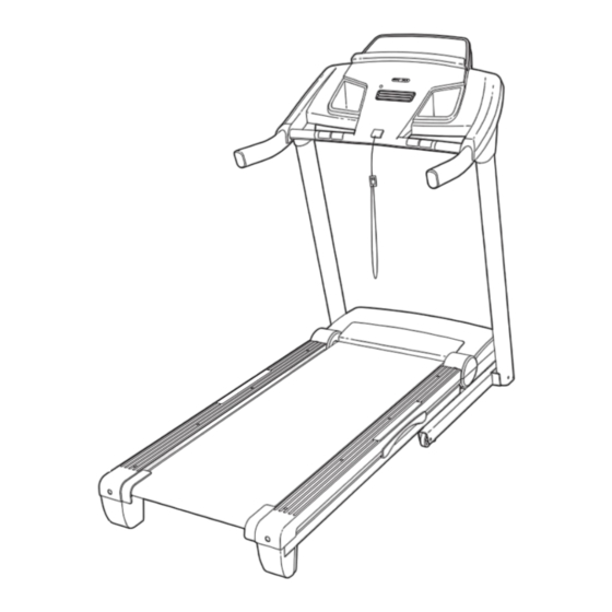
Thank you for selecting the revolutionary EPIC™ CT ing this manual, please see the front cover of this man- 705 treadmill. The CT 705 treadmill offers an impres- ual. To help us assist you, please note the product sive selection of features designed to make your work- model number and serial number before contacting us. -
Page 6: Assembly
ASSEMBLY To hire an authorized service technician to assemble the treadmill, call 1-800-445-2480. Assembly requires two persons. Set the treadmill in a cleared area and remove all packing materials. Do not dispose of the packing materials until assembly is completed. Note: The underside of the treadmill walking belt is coated with high-performance lubricant. - Page 7 1. Make sure that the power cord is unplugged. Hole With the help of a second person, carefully tip the treadmill onto its left side. Partially fold the Frame (55) so that the treadmill is more stable; do not fully fold the Frame yet. Cut the shipping tie securing the Upright Wire (87) to the Base (95).
- Page 8 3. Identify the Right Upright (85) and the Right Upright Spacer (91), which are marked with “Right” stickers. Insert the Upright Wire (87) through the Right Upright Spacer (91) as shown. Set the Right Wire Tie Upright Spacer on the Base (95). See inset drawings B and C.
- Page 9 5. With the help of a second person, carefully tip the treadmill onto its right side. Partially fold the Frame (55) so that the treadmill is more stable; do not fully fold the Frame yet. Attach a Wheel (96) to the Base (95) with a 3/8" x 2"...
- Page 10 7. Identify the Left Upright Cover (80). Slide the Left Upright Cover onto the Left Upright (84). Identify the Left Handrail (82). Remove the tie from the bracket on the Left Handrail. If neces- sary, press the 5/16" Cage Nut (38) back into place.
- Page 11 10. Attach the Crossbar (107) to the Handrails (82, 83) with four #10 x 3/4" Screws (2) and four #10 Star Washers (12). Do not tighten the Screws First yet. Insert the Console Frame (102) into the Handrails (82, 83). Attach the Console Frame with four 1/4"...
- Page 12 12. Set the console assembly on the Left and Right Handrails (82, 83). Be careful not to pinch any Console wires. Insert the excess Upright Wire (87) into Assembly the Right Handrail. Attach the console assembly to the Crossbar (107) with six #8 x 3/4" Screws (1). Start all six Screws before tightening any of them.
- Page 13 14. If necessary, press the Left and Right Trays (103, 104) into the console assembly. Console Assembly 15. Raise the Frame (55) to the position shown. Have a second person hold the Frame until this step is completed. Orient the Storage Latch (51) so that the large barrel and the Latch Knob (52) are oriented as shown.
-
Page 14: Operation And Adjustment
OPERATION AND ADJUSTMENT THE PRE-LUBRICATED WALKING BELT dance with all local codes and ordinances. IMPORTANT: The treadmill is not compatible with GFCI-equipped outlets and may not be compatible Your treadmill features a walking belt coated with high- performance lubricant. IMPORTANT: Never apply sil- with AFCI-equipped outlets. - Page 15 CONSOLE DIAGRAM FEATURES OF THE CONSOLE phone number on the front cover of this manual. iFit cards are also available at select stores. The treadmill console offers an impressive array of features designed to make your workouts more effec- You can even listen to your favorite workout music or tive and enjoyable.
- Page 16 HOW TO TURN ON THE POWER HOW TO USE THE MANUAL MODE IMPORTANT: If the treadmill has been exposed to 1. Insert the key into the console. cold temperatures, allow it to warm to room tem- perature before turning on the power. If you do not See HOW TO TURN ON THE POWER at the left.
- Page 17 4. Change the incline of the treadmill as desired. Speed display—This display shows the speed To change the incline of of the walking belt. the treadmill, press the Incline increase and de- crease buttons or one of the numbered incline To reset the displays, press the Stop button, re- buttons.
- Page 18 HOW TO USE A PRESET WORKOUT Note: The calorie goal is an estimate of the number of calories that you will burn during the 1. Insert the key into the console. workout. The actual number of calories that you burn will depend on your weight. In addi- tion, if you manually change the speed or in- See HOW TO TURN ON THE POWER on page 16.
- Page 19 HOW TO USE AN IFIT WORKOUT 3. Start the walking belt. To purchase iFit cards at any time, go to www.iFit.com Press the Go button or the Speed increase button or call the telephone number on the front cover of this to start the workout.
- Page 20 THE INFORMATION MODE HOW TO USE THE STEREO SOUND SYSTEM The console features an information mode that keeps To play music or audio books through the consoleʼs track of the total number of hours that the treadmill has stereo speakers, you must connect your MP3 player, been used and the total distance that the walking belt CD player, or other personal audio player to the con- has moved.
-
Page 21: How To Fold And Move The Treadmill
HOW TO FOLD AND MOVE THE TREADMILL HOW TO FOLD THE TREADMILL HOW TO MOVE THE TREADMILL To avoid damaging the treadmill, adjust the incline Before moving the treadmill, fold it as described at the to the lowest position before you fold the treadmill. left. -
Page 22: Troubleshooting
TROUBLESHOOTING Most treadmill problems can be solved by following SYMPTOM: The console displays remain lit when the simple steps below. Find the symptom that you remove the key from the console applies, and follow the steps listed. If further assis- tance is needed, see the front cover of this manual. - Page 23 SYMPTOM: The walking belt slows when walked on Next, remove the three #8 x 3/4" Screws (1), and carefully pivot the Motor Hood (62) off. a. Use only a single-outlet surge suppressor that meets all of the specifications described on page 14. b.
- Page 24 SYMPTOM: The walking belt is off-center or slips b. If the walking belt slips when walked on, first re- when walked on move the key and UNPLUG THE POWER CORD. Using the hex key, turn both idler roller screws a. If the walking belt is off-center, first remove the clockwise, 1/4 of a turn.
-
Page 25: Exercise Guidelines
EXERCISE GUIDELINES WARNING: Burning Fat—To burn fat effectively, you must exer- cise at a low intensity level for a sustained period of Before beginning this time. During the first few minutes of exercise, your or any exercise program, consult your physi- body uses carbohydrate calories for energy. -
Page 26: Part List
PART LIST Model No. EPTL69011.0 R0211A To locate the parts listed below, see the EXPLODED DRAWING near the end of this manual. Key No. Qty. Description Key No. Qty. Description #8 x 3/4" Screw Storage Latch #10 x 3/4" Screw Latch Knob 5/16"... - Page 27 Key No. Qty. Description Key No. Qty. Description Console Console Base Console Frame Crossbar Left Tray Access Door Right Tray Console Ground Wire Console Clamp – Userʼs Manual Note: Specifications are subject to change without notice. For information about ordering replacement parts, see the back cover of this manual.
-
Page 28: Exploded Drawing
EXPLODED DRAWING A Model No. EPTL69011.0 R0211A... - Page 29 EXPLODED DRAWING B Model No. EPTL69011.0 R0211A...
- Page 30 EXPLODED DRAWING C Model No. EPTL69011.0 R0211A...
- Page 31 EXPLODED DRAWING D Model No. EPTL69011.0 R0211A...
-
Page 32: Ordering Replacement Parts
ORDERING REPLACEMENT PARTS To order replacement parts, please see the front cover of this manual. To help us assist you, be prepared to pro- vide the following information when contacting us: • the model number and serial number of the product (see the front cover of this manual) •...
Need help?
Do you have a question about the CT 705 and is the answer not in the manual?
Questions and answers