Life Fitness G7 CABLE MOTION User Manual
Hide thumbs
Also See for G7 CABLE MOTION:
- Assembly instructions manual (26 pages) ,
- Specifications (9 pages) ,
- Parts manual (15 pages)

Related Manuals for Life Fitness G7 CABLE MOTION


Summary of Contents for Life Fitness G7 CABLE MOTION
- Page 1 G7 CABLE MOTION ™ GYM SYSTEM USER GUIDE WARNING: Read and follow all directions for each step to insure proper assembly of this product. CLASS H PART # 8352100 REV. A VERSION: LFG7-001 DATE: 08-10-07...
- Page 2 DO NOT attempt to fix. Notify your authorized Life Fitness dealer. 7. Inspect cables and their connections before using machine. Pay particular attention to the cable ends. DO NOT attempt to fix. Notify your authorized Life Fitness dealer before use and have repairs made by an authorized service technician.
-
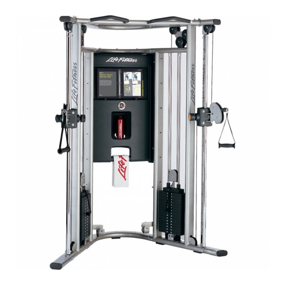
Page 3: Gym Dimensions
GYM DIMENSIONS Weight: 720 lbs Resistance Ratio:... -
Page 4: Components List
COMPONENTS LIST ITEM NO. QTY. PART NO. DESCRIPTION 8172901 LEFT TOWER 8178003 TOP BRACKET TUBE 8178002 MIDDLE BRACKET TUBE 8178004 BOTTOM BRACKET TUBE 8613201 & 8162201 Roller Carriage Assy. (8613201) & Chrome Slide (8162201) 8351601 LEFT SLIDE TUBE (WITH ROLLER CARRIAGE) ASSEMBLY 8257401 RIGHT U BRACKET 8256901... - Page 5 COMPONENTS LIST HARDWARE LISTED BELOW ITEM NO. QTY. PART NO. DESCRIPTION 3256201 M10 X20MM SCREW 3264201 M10 WASHER 3242201 M5 HEX SCREW 3264101 M6 WASHER 3256208 M10 X 55MM SCREW 3256206 M10 X 45MM SCREW 3242002 M10 HEX NYLOCK NUT 3256211 M10 X 70MM SCREW 3264601...
- Page 6 HARDWARE:...
- Page 7 NOTE: Two person assembly is recommended. STEP 1: Make sure the LEFT TOWER (1) and the RIGHT TOWER (11) are positioned correctly prior to assembly. The LEFT U BRACKET (A) and RIGHT U BRACKET (B) should point towards each other as shown in the above illustration. Use four M10 x 20mm SCREWS (26) and four M10 WASHERS (27) to connect the BOTTOM BRACKET TUBE (4) to the LEFT TOWER (1).
- Page 8 STEP 2: Attach the CHIN UP BAR (12) between the LEFT TOWER (1) and RIGHT TOWER (11) using four M10 x 70mm SCREWS (33), eight M10 WASHERS (27), and four M10 HEX NYLOCK NUTS (32). Finger tighten only. NOTE: Make sure the CHIN UP BAR (12) is in the correct position as shown. Tighten all FRAME and CHIN UP BAR screws and nuts securely.
- Page 9 STEP 3: Slide the top of the LEFT SLIDE TUBE ASSEMBLY (5) over the UPPER BRACKET (C) on the LEFT TOWER (1). NOTE: MAKE SURE THE ENGRAVED NUMBERS ON THE LEFT SLIDE TUBE ASSEMBLY (5) FACE THE INSIDE OF THE GYM. NOTE THE ORIENTATION OF THE CARRIAGE. Secure the LEFT SLIDE TUBE ASSEMBLY (5) to the UPPER BRACKET (C) of the LEFT TOWER (1) using one M10 x 45mm SCREW (31), two M10 WASHERS (27), and one M10 HEX NYLOCK NUT (32).
- Page 10 STEP 4: Remove the protective paper from the SIDE SHROUD (23) before installation. Install one SIDE SHROUD (23) to the RIGHT TOWER (11) using sixteen M5 SHOULDER SCREWS (39) on the inside of the SIDE SHROUD (23) into the UPRIGHT TUBES (E) of the RIGHT TOWER (11). Tighten the screws securely.
- Page 11 NOTE: The Side Shroud is not shown in this illustration for clarity. STEP 5 NOTE: INSTALL FROM THE INSIDE OF THE UNIT. Position two WEIGHT STACK CUSHIONS (20) and GUIDE RODS (16) at the GUIDE ROD BRACKET (G) on the RIGHT TOWER (11) as shown.
- Page 12 STEP 6: Uncoil cables to remove all twists. Remove the UPPER PULLEYS (H) on the RIGHT TOWER (11) and LEFT TOWER (1) by removing the M10 x 50mm SCREW (I), PULLEY RETAINER (J), M10 SOCKET HEAD NUT (K), and PARTIAL PULLEY COVERS (L). Set the UPPER PULLEYS (H) and hardware aside.
- Page 13 STEP 7: Insert the threaded end of the CABLE (21) where UPPER PULLEY (H) was located. Lower the CABLE (21) down the long vertical tube that is in front of the gym until it can be retrieved near where the LOWER PULLEY (M) was located.
- Page 14 Quick Connect Assembly - Part Number 7872601 Part Number ITEM QTY. DESCRIPTION 7726201 QUICK CONNECT COUPLER 7726401 QUICK CONNECT HOUSING 7726301 QUICK CONNECT SLEEVE 3249901 QUICK CONNECT SPRING 3250002 M5 HEX SCREW STEP 8: Dissemble one QUICK CONNECT by removing the two M5 HEX SCREWS (T) from the QUICK CONNECT COU- PLER (U).
- Page 15 STEP 9: Make adjustments to the HEAD PLATE PULLEY (19) and the threaded cable end to adjust cable length and to ensure the cable is taut. If the threaded cable end is completely threaded into the ROLLER CARRIAGE (Q) and there is still some slack in the CABLE (21), remove the pulley from the HEAD PLATE PULLEY (19).
- Page 16 STEP 10: Install the FOOT EXTENSIONS (22) to the BOTTOM BRACKET TUBES (4) using four M10 x 20mm SCREWS (26) and four M10 WASHERS (27) on each side.
- Page 17 STEP 11: Attach the six KIOSK BRACKETS (24) to the RIGHT TOWER (11) and LEFT TOWER (1) using two M5 HEX SCREWS (28) and two M6 WASHERS (29) each. Tighten the screws securely. Fasten the KIOSK (25) to the KIOSK BRACKETS (24) using twelve M10 x 20mm SCREWS (40) and twelve 10.5 WASHERS (41).
- Page 18 STEP 12: Adjust the rollers if the ROLLER CARRIAGE (Q) rolls up and down the tube with difficulty, or if it seems to sloppy. Unscrew the cable end from the roller carriage housing. Remove the SCREWS (Y) that hold the two PLASTIC COVERS (Z) together. There are two ROLLER ADJUSTMENT SCREWS (AA), each with a spring, on the back side of the roller carriage housing.
- Page 19 Please note: * We recommend cleaning your product (pads and frame) on a regular basis, using warm soapy water. Touch-up paint can be purchased from your Life Fitness cus- tomer service representative at (800) 351-3737. * Inspect equipment daily. Tighten all loose connections are replace worn parts immediately.
-
Page 20: Limited Warranty
LIMITED WARRANTY ON FRAME AND WELDS. If the frame of the Life Fitness product or a weld should crack or break, it will be repaired or replaced by Life Fitness. Terms: IN HOME USE ONLY: Lifetime – for so long as the Customer owns the Life Fitness product;... - Page 21 Phone: 39 (457) 237811 Japan Fax: 39 (457) 7238197 Phone: 81 (3) 3359-4309 Fax: 81 (3) 3359-4307 Life Fitness Asia Pacific Limited Life Fitness Do Brazil Room 2610, Miramar Tower Al. Rio Negro, 433-Predio 2-Sala 2 132 Nathan Road, Tsimshatsui 3°...
Need help?
Do you have a question about the G7 CABLE MOTION and is the answer not in the manual?
Questions and answers