
Subscribe to Our Youtube Channel
Related Manuals for Life Fitness Cable Motion 39735


Summary of Contents for Life Fitness Cable Motion 39735
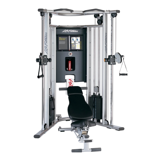
- Page 1 G7 CABLE MOTION ™ GYM SYSTEM ASSEMBLY INSTRUCTIONS G7-002 / CLASS H / 10/14/08 / 8352100 REV. B...
-
Page 2: Table Of Contents
SAFETY INFORMATION It is the sole responsibility of the purchaser of LIFE FITNESS products to read the owner's manual, warning labels and instruct all individuals, whether they are the end user or supervising personnel on proper usage of the equipment. - Page 3 6. Ensure that any person(s) making adjustments or performing maintenance or repair of any kind is qualified to do so. LIFE FITNESS will provide service and maintenance training at our corporate facility upon request or in the field if proper arrangements are made.
-
Page 4: G7 Warning Labels
G7 WARNING LABELS Schiller Park, IL www.lifefitness.com Model: FZCP- Serial Number: Class: S - Studio Maximum User Weight: 300 lbs (136kg) NOTE: Lock the weight stack when not using the gym. Make sure all the weight plates are resting on the plate below with no gap in between. -
Page 5: Gym Dimensions
Weight: 720 lbs Resistance Ratio: Weight Stack: 160 lbs GYM DIMENSIONS... -
Page 6: G7 Live Area
G7 LIVE AREA 12” 12” 10’ 18’-8” NOTE: The live area shows the extent of the G7 gym. It does not include the user. -
Page 7: Components List
COMPONENTS LIST ITEM NO. QTY. DESCRIPTION LEFT TOWER TOP BRACKET TUBE MIDDLE BRACKET TUBE BOTTOM BRACKET TUBE LEFT SLIDE TUBE (WITH ROLLER CARRIAGE) ASSEMBLY RIGHT U BRACKET LEFT U BRACKET RIGHT SWIVEL PULLEY LEFT SWIVEL PULLEY RIGHT SLIDE TUBE (WITH ROLLER CARRIAGE) ASSEMBLY RIGHT TOWER CHIN UP BAR PULLEY... -
Page 8: Components List
COMPONENTS LIST HARDWARE ITEM NO. QTY. BLISTER PACKS Blister Pack 7-1 Blister Pack 7-2 Blister Pack 7-3 Blister Pack 7-4 Blister Pack 7-5 Blister Pack 7-6 REQUIRED TOOLS ADJUSTABLE WRENCH EXTERNAL SNAP RING PLIERS PHILLIPS SCREW DRIVER ALLEN WRENCHES (4mm, 5mm, 7mm) WRENCH (17mm) DESCRIPTION M10 X 20MM SCREW... - Page 9 HARDWARE: M5 HEX SCREW (#45) M10 X 20MM SCREW (#43) M10 WASHER (#44) M10 X 55MM SCREW (#47) M6 WASHER (#46) M10 X 45MM SCREW (#48) M10 HEX NYLOCK NUT (#49) M10 SOCKET NUT (#51) M10 X 50MM SCREW (#52) M10 X 70MM SCREW (#50) M10 X 50MM HEX TENSION SCREW (#55) PULLEY RETAINER (#53)
-
Page 10: Assembly Instructions
NOTE: Two person assembly is recommended. STEP 1: Use the following hardware contained in Blister Pack (7-1): M10 x 20mm SCREW (Qty. 24) M10 WASHER (Qty. 24) Make sure the LEFT TOWER (1) and the RIGHT TOWER (11) are positioned correctly prior to assembly. The LEFT U BRACKET (A) and RIGHT U BRACKET (B) should point towards each other as shown in the above illustration. - Page 11 STEP 2: Use the following hardware contained in Blister Pack (7-1): M10 x 70mm SCREW (Qty. 4) M10 WASHER (Qty. 8) M10 HEX NYLOCK NUT (Qty. 4) Attach the CHIN UP BAR (12) between the LEFT TOWER (1) and RIGHT TOWER (11) using four M10 x 70mm SCREWS (50), eight M10 WASHERS (44), and four M10 HEX NYLOCK NUTS (49).
- Page 12 STEP 3: Use the following hardware contained in Blister Pack (7-2): M10 x 45mm SCREW (Qty. 2) M10 WASHER (Qty. 8) M10 HEX NYLOCK NUT (Qty. 4) M10 x 55mm SCREW (Qty. 2) Slide the top of the LEFT SLIDE TUBE ASSEMBLY (5) over the UPPER BRACKET (C) on the LEFT TOWER (1). NOTE: MAKE SURE THE ENGRAVED NUMBERS ON THE LEFT SLIDE TUBE ASSEMBLY (5) FACE THE INSIDE OF THE GYM.
- Page 13 STEP 4: Use the following hardware contained in Blister Pack (7-2): M5 SHOULDER SCREW (Qty. 32) M5 HEX SCREW (Qty. 8) M6 WASHER (Qty. 8) Remove the protective paper from the SIDE SHROUD (23) before installation. Install one SIDE SHROUD (23) to the RIGHT TOWER (11) using sixteen M5 SHOULDER SCREWS (56) on the inside of the SIDE SHROUD (23) into the UPRIGHT TUBES (E) of the RIGHT TOWER (11).
- Page 14 STEP 5: Use the following hardware contained in Blister Pack (7-3): M10 x 50mm HEX TENSION SCREW (Qty. 4) GUIDE ROD RETAINER (Qty. 4) RETAINER RING (Qty. 4) NOTE: INSTALL FROM THE INSIDE OF THE UNIT. Position two WEIGHT STACK CUSHIONS (20) and GUIDE RODS (16) at the GUIDE ROD BRACKET (G) on the RIGHT TOWER (11) as shown.
- Page 15 Upper Pulley Lower Pulley STEP 6: Uncoil the cables to remove all twists. Remove the (UPPER) PULLEYS (13) on the RIGHT TOWER (11) and LEFT TOWER (1) by removing the M10 x 50mm SCREW (52), PULLEY RETAINER (53), M10 SOCKET HEAD NUT (51), and PARTIAL PULLEY COVERS (14).
- Page 16 Middle Upper Pulley Upper Pulley Lower Pulley STEP 7: Use the following hardware contained in Blister Packs (7-3), (7-4) and (7-5): M10 WASHER (Qty. 4) M10 HEX NYLOCK NUT (Qty. 2) M10 x 45mm SCREW (Qty. 2) M10 SOCKET HEAD NUT (Qty. 2) M10 x 50mm SCREW (Qty.
- Page 17 Slide Mechanism to insert or Exchange Handles STEP 8: Dissemble one QUICK CONNECT by removing the two M5 HEX SCREWS (M) from the QUICK CONNECT COU- PLER (I). Carefully remove the QUICK CONNECT SPRING (L), the QUICK CONNECT SLEEVE (K) and the QUICK CONNECT HOUSING (J).
- Page 18 STEP 9: Make adjustments to the HEAD PLATE PULLEY (19) and the threaded cable end to adjust cable length and to ensure the cable is taut. If the threaded cable end is completely threaded into the LEFT ROLLER CARRIAGE (28) and there is still some slack in the CABLE (21), remove the pulley from the HEAD PLATE PULLEY (19).
- Page 19 STEP 10: Use the following hardware contained in Blister Pack (7-4): M10 x 20mm SCREW (Qty. 8) M10 WASHER (Qty. 8) Install one FOOT EXTENSION (22) to the bottom of the LEFT TOWER (1) using four M10 x 20mm SCREWS (43) and four M10 WASHERS (44).
- Page 20 STEP 11: Use the following hardware contained in Blister Pack (7-6): M5 HEX SCREW (Qty. 12) M6 WASHER (Qty. 12) M10 x 16mm SCREW (Qty. 12) M10.5 WASHER (Qty. 12) M10 x 70mm SCREW (Qty. 3) M10 WASHER (Qty. 6) M10 HEX NYLOCK NUT (Qty.
- Page 21 STEP 12: Adjust the rollers if the ROLLER CARRIAGE (28) rolls up and down the tube with difficulty, or if it seems to sloppy. Unscrew the cable end from the roller carriage housing. Remove the SCREWS (N) that hold the two PLASTIC COVERS (O) together. There are two ROLLER ADJUSTMENT SCREWS (P), each with a spring, on the back side of the roller carriage housing.
- Page 22 STEP 13: The G7 comes with the following accessories: THIGH STRAP (31), FOOT STRAP (32), HANDLES (35), SNAP LINKS (36), LONG BAR (41), and EXERCISE BALL (39).
- Page 23 STEP 14: Use the FRONT HANDLE (Q) to tilt the bench. Steer the bench to align with the U BRACKETS (R). Insert one PIN (S) into each bracket so the bench is restrained.
-
Page 24: General Maintenance
Please note: * We recommend cleaning your product (pads and frame) on a regular basis, using warm soapy water. Touch-up paint can be purchased from your Life Fitness cus- tomer service representative at (800) 351-3737. * Inspect equipment before each use. Tighten all loose connections are replace worn parts immediately. -
Page 25: Warranty Statement
LIMITED WARRANTY ON FRAME AND WELDS. If the frame of the Life Fitness product or a weld should crack or break, it will be repaired or replaced by Life Fitness. Terms: IN HOME USE ONLY: Lifetime – for so long as the Customer owns the Life Fitness product;... -
Page 26: Contact Information
Nippon Brunswick Bldg., #8F 5-27-7 Sendagaya Shibuya-Ku, Tokyo Japan 151-0051 Telephone: (+81) 3.3359.4309 Fax: (+81) 3.3359.4307 China and Hong Kong Life Fitness Asia Pacific LTD Room 2610, Miramar Tower 132 Nathan Road Tsimshatsui, Kowloon HONG KONG Telephone: (+852) 2891.6677 Fax: (+852) 2575.6001 All Other Asia Pacific countries &...
Need help?
Do you have a question about the Cable Motion 39735 and is the answer not in the manual?
Questions and answers