KitchenAid 30" Installation Instructions And Use & Care Manual
30" (76.2 cm) and 36" (91.4 cm) retractable (pop-up) downdraft vent system
Hide thumbs
Also See for 30":
- Installation instructions and use & care manual (56 pages) ,
- Installation instructions and use and care manual (36 pages) ,
- Use & care manual (32 pages)
Table of Contents
Advertisement
Available languages
Available languages
Quick Links
30" (76.2 CM) AND 36" (91.4 CM)
RETRACTABLE (POP-UP) DOWNDRAFT VENT
SYSTEM
Installation Instructions and Use & Care Guide
SYSTÈME DE VENTILATION RÉTRACTABLE
(CLAPET) DE 30" (76,2 CM) ET 36" (91,4 CM) -
ASPIRATION PAR LE BAS
Instructions d'installation et Guide d'utilisation et d'entretien
Table of Contents/Table des matières............................................................................. 2
IMPORTANT: READ AND SAVE THESE INSTRUCTIONS.
FOR RESIDENTIAL USE ONLY.
IMPORTANT : LIRE ET CONSERVER CES INSTRUCTIONS.
POUR UTILISATION RÉSIDENTIELLE UNIQUEMENT.
W10187117C
Advertisement
Table of Contents

Related Manuals for KitchenAid 30"


Summary of Contents for KitchenAid 30"
- Page 1 30" (76.2 CM) AND 36" (91.4 CM) RETRACTABLE (POP-UP) DOWNDRAFT VENT SYSTEM Installation Instructions and Use & Care Guide SYSTÈME DE VENTILATION RÉTRACTABLE (CLAPET) DE 30" (76,2 CM) ET 36" (91,4 CM) - ASPIRATION PAR LE BAS Instructions d’installation et Guide d’utilisation et d’entretien Table of Contents/Table des matières................
-
Page 2: Table Of Contents
TABLE OF CONTENTS TABLE DES MATIÈRES VENT SYSTEM SAFETY..............3 SÉCURITÉ DU SYSTÈME DE VENTILATION ......25 INSTALLATION REQUIREMENTS ..........4 EXIGENCES D'INSTALLATION ...........27 Tools and Parts ................4 Outillage et pièces..............27 Location Requirements ..............4 Exigences d'emplacement............27 Electrical Requirements ...............7 Spécifications électriques ............30 Venting Requirements..............7 Exigences concernant l'évacuation ...........30 INSTALLATION INSTRUCTIONS INSTRUCTIONS D'INSTALLATION... -
Page 3: Vent System Safety
VENT SYSTEM SAFETY Your safety and the safety of others are very important. We have provided many important safety messages in this manual and on your appliance. Always read and obey all safety messages. This is the safety alert symbol. This symbol alerts you to potential hazards that can kill or hurt you and others. -
Page 4: Installation Requirements
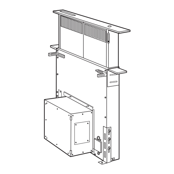
INSTALLATION REQUIREMENTS Tools and Parts Location Requirements Gather the required tools and parts before starting installation. NOTE: Downdraft vent is installed directly behind the cooktop. Read and follow the instructions provided with any tools listed Install the downdraft vent first, then install the cooktop. here. - Page 5 Product Dimensions Interior-mounted blower motor model Exterior-mounted blower motor model - used with Part Number KPEC992M Top trim widths: 30¹⁄₄" (76.8 cm) for 30" (76.2 cm) vent 36¹⁄₄" (92.1 cm) for 36" (91.4 cm) vent 13¹⁄₂" (34.3 cm) ¹⁄₄" (0.6 cm) retractable vent height 13"...
- Page 6 Countertop Cutout Dimensions IMPORTANT: Countertops with a bull-nosed front edge are not recommended for these installations. Some models require a countertop deeper than 25" (63.5 cm); see the following Countertop Cutout Dimensions Chart. To avoid mistakes, it is recommended that the cooktop and vent cutouts be drawn on the countertop before making any cutouts. See Cooktop Installation Instructions for complete cutout dimensions, location dimensions and installation details.
-
Page 7: Electrical Requirements
Electrical Requirements IMPORTANT: Observe all governing codes and ordinances. Save The downdraft vent must be connected with copper wire Installation Instructions for electrical inspector’s use. only. It is the customer’s responsibility to contact a qualified electrical The downdraft vent should be connected directly to the installer, and to ensure that the electrical installation is adequate circuit breaker (or fused disconnect) box through flexible and in conformance with National Electrical Code, ANSI/NFPA 70... -
Page 8: Installation Instructions Interior-Mounted Vent Motor
INSTALLATION INSTRUCTIONS INTERIOR-MOUNTED VENT MOTOR Venting Methods - Interior Mounted Vent Motor Only Island Location Determine which venting method is best for your application. Vent system can terminate either through the wall or floor. Vent system installed under a concrete slab using PVC sewer pipe. -
Page 9: Install Vent System
Maximum Length of Vent System The following example falls within the maximum vent length of 35 ft (8.9 m). Vent Length 2 - 90° elbow = 10.0 ft (3 m) 6" (15.2 cm) round 35 ft (8.9 m) 1 - wall cap = 0.0 ft (0.0 m) 3¹⁄₄"... - Page 10 6. Attach support legs to the side of the downdraft vent with 2 screws in each leg. Do not tighten screws. A. Blower motor box B. Support leg 7. Using 2 or more people, insert the downdraft vent into the A.
- Page 11 5. Tilt blower box top tab so it is flush with the vent box panel 3. Disconnect the wire connector from the blower motor. and position it under the top mounting bracket. Slide bracket in the “Z” slots and tighten the 2 hex/slotted head screws to secure.
- Page 12 7. Plug in the wire connector to the blower motor. 10. Place the bottom tab of the blower box into the bottom mounting channel. A. Blower box A. Blower motor B. Bottom mounting channel B. Wire connector 11. Tilt blower box top tab so it is flush with the vent box panel 8.
-
Page 13: Rear Mounting - Blower Motor
Rear Mounting - Blower Motor NOTE: Optional blower motor mounting position (opposite side). 3. Disconnect the wire connector from the blower motor. The blower motor box assembly can also be moved to the opposite side (rear) of the vent box. A. - Page 14 6. Install the blower motor box assembly to the opposite side 9. Reinstall panel to front side of vent box panel. Place bottom (rear) of the vent box with the vent located in the bottom tab of the panel into the bottom mounting channel. venting position.
-
Page 15: Complete Installation
Complete Installation Make Electrical Connections (Interior Mounted Motor) WARNING 1. Attach backdraft damper over 6" vent extension. Secure with vent clamp. Electrical Shock Hazard Disconnect power before servicing. Replace all parts and panels before operating. Failure to do so can result in death or electrical shock. 1. -
Page 16: Check Operation
5. Connect the 2 black wires together using UL listed wire 6. Replace the terminal box cover and secure with screw. connectors. 7. Reconnect power. Check Operation 1. Push and hold the button on the top of the downdraft vent for 2. -
Page 17: Install Vent System
Roof Venting The following example falls within the maximum vent length of 40 ft (12.2 m). 2 - 90° elbows = 10.0 ft (3 m) 10 ft (3 m) straight = 10.0 ft (3 m) Length of 10" (25.4 cm) = 20 ft (6 m) system NOTE: The exterior-mounted vent motor requires a separate... - Page 18 5. Attach the left and right side end caps to the downdraft vent. Determine which venting direction is best for your Place the end cap upon the overcounter support, slide the installation. tab into the slot and snap into place over the the plastic tabs. When installed in a cabinet, vent system can exhaust through the front or rear of the vent box.
-
Page 19: Complete Installation
3. Reinstall both panels to the opposite side of the vent box 2. Determine the location where the exterior blower box will be panel from which they were removed. Place bottom tab of the located. Cut opening in roof or wall for vent system to exterior panel into the bottom mounting channel. -
Page 20: Check Operation
3. Remove vent box knockout and install a UL listed or CSA approved conduit connector. Feed exterior-mounted vent Check Operation motor wiring through conduit connector. 1. Push and hold the button on the top of the downdraft vent for a few seconds. The retractable section of the downdraft vent will rise. -
Page 21: Vent System Use
VENT SYSTEM USE The retractable downdraft vent system is designed to remove 2. Slide the control slider on the right-hand side of the smoke, cooking vapors and odors from the cooktop area. downdraft vent to adjust the blower motor speed. For best results, the vent should be operating before cooking When cooking is complete: is started. -
Page 22: Wiring Diagram
WIRING DIAGRAM SPEED PUSH BUTTON REGULATION UP/DOWN 5x20 800 mA Time Delay FUSE GEAR MOTOR FILTER SWITCHES FLAT CABLE TOROIDAL TRANSFORMER VDR1 ELDD SIDE INSERT CABLES REMOTE INTERNAL BLOWER BLOWER LINE IN 120 Vac 60 Hz... -
Page 23: Assistance Or Service
For model series KIRD and YKIRD 861, 862 Pages. 36" (91.4 cm) one-piece trim: For further assistance Part Number W10187285 (black) If you need further assistance, you can write to KitchenAid with any questions or concerns at: KitchenAid Brand Home Appliances Customer eXperience Center 553 Benson Road Benton Harbor, MI 49022-2692 Please include a daytime phone number in your correspondence. -
Page 24: Warranty
KitchenAid brand of Whirlpool Corporation or Whirlpool Canada LP (hereafter “KitchenAid”) will pay for Factory Specified Parts and repair labor to correct defects in materials or workmanship. Service must be provided by a KitchenAid designated service company. This limited warranty is valid only in the United States or Canada and applies only when the major appliance is used in the country in which it was purchased. -
Page 25: Sécurité Du Système De Ventilation
SÉCURITÉ DU SYSTÈME DE VENTILATION Votre sécurité et celle des autres est très importante. Nous donnons de nombreux messages de sécurité importants dans ce manuel et sur votre appareil ménager. Assurez-vous de toujours lire tous les messages de sécurité et de vous y conformer. Voici le symbole d’alerte de sécurité. - Page 26 IMPORTANTES INSTRUCTIONS DE SÉCURITÉ AVERTISSEMENT : POUR MINIMISER LE RISQUE AVERTISSEMENT : POUR RÉDUIRE LE RISQUE D'UN FEU DE GRAISSE SUR LA CUISINIÈRE : D'INCENDIE, CHOC ÉLECTRIQUE OU DOMMAGES CORPORELS, RESPECTER LES INSTRUCTIONS Ne jamais laisser un élément de surface fonctionner à SUIVANTES : puissance de chauffage maximale sans surveillance.
-
Page 27: Exigences D'installation
EXIGENCES D'INSTALLATION Connecteurs de fils (homologation UL) (4) Outillage et pièces Câblage pour ventilateur installé à distance (option) Rassembler les outils et pièces nécessaires avant de commencer l'installation. Lire et observer les instructions fournies avec les Exigences d'emplacement outils de cette liste. REMARQUE : Le système d’extraction par le bas est installé... - Page 28 Dimensions du produit Modèle avec ventilateur monté à l'intérieur Modèle avec ventilateur monté à l'extérieur - Utilisation avec le produit n˚ KPEC992M Garniture supérieure : 30¹⁄₄" (76,8 cm) pour système d’extraction de 30" (76,2 cm) 36¹⁄₄" (92,1 cm) pour système d’extraction de 36"...
- Page 29 Plan de travail - Dimensions des ouvertures à découper IMPORTANT : Les plans de travail avec bords arrondis ne sont pas recommandés pour ces installations. Certains modèles nécessitent un plan de travail de plus de 25" (63,5 cm); voir le tableau des dimensions de l'ouverture du plan de travail.
-
Page 30: Spécifications Électriques
Spécifications électriques IMPORTANT : Observer les dispositions de tous les codes et Le système d’extraction par le bas doit être raccordé au règlements en vigueur. Conserver les instructions d'installation réseau électrique uniquement avec des conducteurs de pour consultation par l'inspecteur des installations électriques. cuivre. -
Page 31: Instructions D'installation Ventilateur Monté À L'intérieur
INSTRUCTIONS D'INSTALLATION VENTILATEUR MONTÉ À L'INTÉRIEUR Méthodes d'extraction - Seulement pour un ventilateur monté à l'intérieur Configuration de cuisine en îlot Déterminer quelle méthode d’extraction est la plus appropriée. La sortie à l'extérieur du système d’extraction peut se faire à Système d’extraction installé... -
Page 32: Installation Du Système D'extraction
Pour calculer la longueur effective du système d’extraction nécessaire, additionner les longueurs équivalentes (pieds/mètres) Installation du système d’extraction de tous les composants utilisés dans le système. Composant Système de diamètre 6" (15,2 cm) AVERTISSEMENT coude à 45° 2,5 pi Risque du poids excessif (0,8 m) Utiliser deux ou plus de personnes pour déplacer et installer le système d’extraction. - Page 33 6. Fixer les pieds de support sur les côtés de l'appareil - 2 vis pour chaque pied. Ne pas serrer les vis. A. Boîte du moteur de ventilateur B. Support 7. Faire intervenir 2 personnes ou plus, insérer le système A.
- Page 34 5. Incliner la patte supérieure de la boîte du ventilateur pour la 3. Débrancher le connecteur du câblage du moteur du placer en affleurement avec le panneau de la boîte du ventilateur. système d’extraction et la positionner sous la bride de montage supérieure.
- Page 35 7. Brancher le connecteur du câblage sur le moteur du 10. Placer la patte inférieure de la boîte du ventilateur dans le ventilateur. profilé de montage inférieur. A. Boîte du système d’extraction B. Profilé de montage inférieur A. Moteur du ventilateur B.
-
Page 36: Montage Du Ventilateur À L'arrière
Montage du ventilateur à l'arrière REMARQUE : Position de montage du moteur du ventilateur 2. Dégager la boîte du ventilateur du profilé de montage facultative (côté opposé). On peut également déplacer la boîte du inférieur en la soulevant. moteur du ventilateur du côté opposé (arrière) du circuit d’évacuation. - Page 37 5. Dégager le panneau du profilé de montage inférieur en le 8. Faire basculer l’onglet supérieur de la boîte du ventilateur de soulevant. façon à ce qu’il soit en affleurement avec le panneau de la boîte du système d'extraction et le placer sous la bride de montage supérieure.
-
Page 38: Achever L'installation
Achever l'installation (Moteur monté à l'intérieur) 1. Connecter le clapet anti-reflux au raccord d’extension de 6". Le fixer avec la bride de fixation. A. Lors de la fixation des brides sous le plan de travail, veiller à utiliser des vis de longueur appropriée, qui ne traverseront pas le plan de travail lors du serrage. -
Page 39: Contrôle Du Fonctionnement
4. Connecter ensemble les deux connecteurs blancs avec un Pour des renseignements sur la commande, voir la section connecteur de fils (homologation UL). “Assistance ou service”. A. Garniture supérieure B. Bouton Marche/Arrêt C. Bouton de commande du ventilateur D. Embout E. -
Page 40: Instructions D'installation Ventilateur Monté À L'extérieur
INSTRUCTIONS D'INSTALLATION VENTILATEUR MONTÉ À L'EXTÉRIEUR IMPORTANT : Le ventilateur extérieur modèle n° KPEU722M Décharge à travers le toit [1200 cfm (34 m³/3)] n'est pas utilisable avec ce système d'extraction rétractable. REMARQUE : Pour un système avec ventilateur monté à l'extérieur, on doit utiliser un ventilateur modèle no KPEC992M [900 cfm (25,5 m³/3)], disponible chez un revendeur ou distributeur de pièces agréé. -
Page 41: Installation Du Système D'extraction
Exemple de système d’extraction 5. Fixer les embouts à gauche et à droite sur l'appareil. Placer l’embout sur le support du plan de travail, faire glisser l’onglet dans la fente et l’emboîter sur les onglets en plastique. A. Ventilateur externe B. -
Page 42: Achever L'installation
Placer la patte inférieure du panneau dans le profilé de Déterminer la meilleure direction pour l’installation. montage inférieur. Dans le cas de l’installation dans un placard, on peut effectuer la décharge du système d’extraction par l'avant et par l'arrière de la boîte du système d'extraction. -
Page 43: Raccordement Électrique
2. Déterminer l'emplacement où le ventilateur extérieur sera installé. Découper l'ouverture appropriée dans le toit ou le Raccordement électrique mur pour le passage du système d’extraction jusqu'au ventilateur extérieur. Exécuter l'installation du ventilateur AVERTISSEMENT extérieur conformément aux instructions fournies avec le ventilateur. -
Page 44: Contrôle Du Fonctionnement
On peut trouver chez le revendeur local des ensembles de AVERTISSEMENT garniture assortis à la couleur du plan de travail. Pour des renseignements sur la commande, voir la section “Assistance ou service”. Risque d'incendie Relier le ventilateur à la terre. Utiliser du fil en cuivre. -
Page 45: Utilisation Du Système D'extraction
UTILISATION DU SYSTÈME D'EXTRACTION La fonction du système d’extraction par le bas est d'aspirer et 2. Pour sélectionner la vitesse du ventilateur, utiliser le bouton évacuer hors de la cuisine les vapeurs et fumées de cuisson, de commande (côté droit) du système d’extraction par le bas. sources d'odeurs. -
Page 46: Schéma De Câblage
SCHÉMA DE CÂBLAGE RÉGULATEUR BOUTON POUSSOIR DE VITESSE HAUT/BAS Fusible temporisé, 5x20 800 mA FUSIBLE MOTEUR ROUGE ROUGE NOIR NOIR (ENGRENAGES) COMMUTATEURS (FILTRE) GRIS GRIS CÂBLE PLAT TRANSFORMATEUR TOROÏDAL VDR1 (connecteur) (connecteurs) ORANGE GRIS GRIS BLANC BLANC NOIR BLANC MARRON BLEU L1 (phase) ELDD... -
Page 47: Assistance Ou Service
REMARQUE : Instructions d'installation fournies avec chaque de rechange et compagnies de service. Les techniciens de ensemble. service désignés par KitchenAid sont formés pour effectuer Pour les modèles séries KIRD et YKIRD 801, 802 les travaux de réparation sous garantie et le service après la garantie, partout aux États-Unis. -
Page 48: Garantie
5. Les défauts apparents, notamment les éraflures, les bosses, fissures ou tout autre dommage au fini du gros appareil ménager, à moins que ces dommages soient dus à des vices de matériaux ou de fabrication et soient signalés à KitchenAid dans les 30 jours suivant la date d’achat.
Need help?
Do you have a question about the 30" and is the answer not in the manual?
Questions and answers