
Related Manuals for MULTIQUIP GA3.6H


Summary of Contents for MULTIQUIP GA3.6H
- Page 1 OPERATION AND PARTS MANUAL MODEL GA3.6H Series GA-3.6HZ GA3.6H GA3.6HA Portable Generators (HONDA GASOLINE ENGINE) Revision #0 (11/01/05) THIS MANUAL MUST ACCOMPANY THE EQUIPMENT AT ALL TIMES.
-
Page 2: Proposition 65 Warning
PAGE 2 — GA-3.6H SERIES A.C. GENERATORS — OPERATION & PARTS MANUAL — REV. #0 (11/01/05) - Page 3 NOTE PAGE GA-3.6H SERIES A.C. GENERATORS — OPERATION & PARTS MANUAL — REV. #0 (11/01/05) — PAGE 3...
-
Page 4: Table Of Contents
Multiquip GA-3.6H Series AC Portable Generators Proposition 65 Warning ... 2 Table Of Contents ... 4 Parts Ordering Procedures ... 5 Safety Message Alert Symbols ... 6-7 Rules for Safe Operation ... 8-10 Specifications (Generator/Engine) ... 11 Dimensions ... 12 General Information ... -
Page 5: Parts Ordering Procedures
Effective: June 1 , 2005 Ordering parts has never been easier! Order via Internet Best Deal! Order parts on-line using Multiquip’s SmartEquip website! ■ View Parts Diagrams ■ Order Parts ■ Print Specification Information Goto www.multiquip.com and click on Order Order via Fax All customers are welcome to order parts via Fax. -
Page 6: Safety Message Alert Symbols
GA-3.6H Series — SAFETY MESSAGE ALERT SYMBOLS FOR YOUR SAFETY AND THE SAFETY OF OTHERS! Safety precautions should be followed at all times when operating this equipment. Failure to read and understand the Safety Messages and Operating Instructions could result in injury to yourself and others. -
Page 7: Safety Message Alert Symbols
GA-3.6H SERIES A.C. GENERATORS — OPERATION & PARTS MANUAL — REV. #0 (11/01/05) — PAGE 7 Equipment Damage CAUTION CAUTION CAUTION CAUTION CAUTION Other important messages are provided throughout this manual to help prevent damage to your portable generator, other property, or the surrounding environment. Hazards... -
Page 8: General Safety
This equipment is for industrial use only. The following safety guidelines should always be used when operating the GA-3.6H Series Portable Generator: GENERAL SAFETY ■ DO NOT operate or service this equipment before reading this entire manual. -
Page 9: Rules For Safe Operation
■ ALWAYS be sure the operator is familiar with proper safety precautions and operation techniques before using generators. ■ NEVER leave the generators unattended, turn off engine when unattended. ■ Unauthorized equipment modifications will void all warranties. ■ ALWAYS ensure generators are on level ground before use. ■... - Page 10 DANGER DANGER DANGER ELECTROCUTION HAZARDS ELECTROCUTION HAZARDS ELECTROCUTION HAZARDS DANGER DANGER ELECTROCUTION HAZARDS ELECTROCUTION HAZARDS During operation of this generation, there exists the possibility of electrocution , electrical shock or burn , which can cause severe bodily harm or even DEATH! To avoid these hazards: NEVER use damaged or worn cables when connecting...
-
Page 11: Specifications (Generator/Engine)
GA-3.6H Series— SPECIFICATIONS (GENERATOR/ENGINE) t a r l e u t r a Effects of Altitude and Heat The maximum output of the engines listed above are applicable to supplying electrical power for continuous service at ambient conditions in accordance with SAE Test cord J607. The above ambient conditions are at standard sea level, with a barometric reading of 29.92 inches and a temperature of 60 degrees fahrenheit. -
Page 12: Dimensions
GA-3.6H Series— DIMENSIONS Figure 2. Dimensions PAGE 12 — GA-3.6H SERIES A.C. GENERATORS — OPERATION & PARTS MANUAL — REV. #0 (11/01/05) -
Page 13: General Information
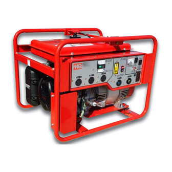
WARNING WARNING WARNING WARNING WARNING Before connecting this generators to any building’s electrical system, a licensed electrician must install an isolation (transfer) switch. Serious injury or death may result without this transfer switch.F GA-3.6H Series Familiarzation Generator The Multiquip GA-3.6H series generators have been designed as a portable dual purpose power source for 60 Hz (single phase) lighting facilities, power tools, submersible pumps and other industrial and construction machinery. -
Page 14: Load Application
Single Phase Load — 60 Hz Always be sure to check the nameplate on the generators and equipment to insure the wattage, amperage and frequency requirements are satisfactorily supplied by the generators for operating the equipment. Generally, the wattage listed on the nameplate of the equipment is its rated output. -
Page 15: Controls And Indicators
Lifting Bail Eye – Attach a rope or chain to this lifting eye when lifting of the generators is required. Never stand underneath the generators while it is being lifted. Place lifting eye in down position when not in use. AC-Voltmeter –... -
Page 16: Controls And Indicators
Model GA3.6HZ shown. Location of Full Power Switch for Models GA3.6H and NOTE GA-3.6HA, is on front control panel. 11. Full Power Switch – The generators are provided with a full power switch. Figures 2C and 2D show simplified wiring diagrams of the dual voltage system. - Page 17 Models GA3.6H and GA3.6HA shown. Componet location for GA3.6HZ is NOTE similar. Figure 2E. Generators Components 14. Fuel Cock Lever – Turn this lever downward to start (down)the flow of fuel into the carburetor. Turn upward to stop ( up ) the flow of fuel.
-
Page 18: Generator Refueling
DANGER DANGER DANGER DANGER DANGER Adding fuel to the tank should be done only when the engine is stopped and has had an opportunity to cool down. In the event of a fuel spill, DO NOT attempt to start the engine until the fuel residue has been completely wiped up, and the area surrounding the engine is dry. -
Page 19: Installation
Outdoor Installation Install the generator/welder in a area that is free of debris , bystanders , and overhead obstructions . Make sure the generators is on secure level ground so that it cannot slide or shift around. Also install the generators in a manner so that the exhaust will not be discharged in the direction of nearby homes. - Page 20 GA-3.6H Series — INSTALLATION Connecting the Ground The nut and ground terminal on the generators should always be used to connect the generators to a suitable ground. The ground cable should be #8 size wire minimum. At the generator, connect the terminal of the ground cable between the lock washer and the nut (Figure 4) and tighten the nut fully.
-
Page 21: Pre-Inspection
General Inspection Prior to Operation Ground Power Tools When using power tools or electrical equipment requireing AC power from the generator, make sure connecting (power tool) cable has a ground as shown in Figure 5. Figure 5. Ground Cables/Plugs GA-3.6H SERIES A.C. GENERATORS — OPERATION & PARTS MANUAL — REV. #0 (11/01/05) — PAGE 21 GA-3.6H Series —... -
Page 22: Pre-Inspection (Engine)
CAUTION CAUTION CAUTION CAUTION CAUTION NEVER operate the generators in a confined area or enclosed area structure that does not provide ample free flow of air . ALWAYS wear approved eye and hearing protection before operating the generator. Before Starting Read safety instructions at the beginning of manual. -
Page 23: Initial Start-Up (Engine)
. This section is intended to assist the operator with the initial start-up of the portable generator. It is extremely important that this section be read carefully before attempting to use the generators in the field. -
Page 24: Initial Start-Up/Generator Operation
GA-3.6H Series— INITIAL START-UP/GENERATOR OPERATION 6. If the engine has started, slowly return the choke lever (Figure 11) to the “OPEN” position. If the engine has not started repeat steps 1 through 5. 7. Before the generator is placed into operation, run the engine for 3-5 minutes. -
Page 25: Generator Operation/Shutdown
GA-3.6H Series— GENERATOR OPERATION/SHUTDOWN 5. Read the voltmeter on the front panel of the generator (Figure 20) and verify that 240 VAC is present at the 240V twist-lock receptacle. Using an external voltmeter verify that 120V is present at the 120V twist-lock and GFCI duplex receptacles. -
Page 26: Preparation For Long Term Storage
GA-3.6H Series— PREPARATION FOR LONG TERM STORAGE Generators Storage For storage of the generating set for over 30 days, the following is required: ■ Drain the fuel tank completely, or add STA-BIL to the fuel. ■ Run the engine until the gasoline in the carburetor is completely consumed. - Page 27 Use Table 5 as a general maintenance guideline when servicing your engine. For more detail engine maintenance information, refer to the engine owner's manual supplied with your engine. ) 3 ( l i O r i A g i t l l A &...
-
Page 28: Maintenance (Engine)
Maintenance Perform the scheduled maintenance procedures as defined by Table 6 and below: DAILY ■ Thoroughly remove dirt and oil from the engine and control area. Clean or replace the air cleaner elements as necessary. Check and retighten all fasteners as necessary. Check the gearbox for oil leaks. -
Page 29: Wiring Diagram (Ga-3Hz Generator)
GA-3.6H Series — WIRING DIAGRAM (3.6HZ) GA-3.6HZ WIRING DIAGRAM Figure 28. Generator Wiring Diagram (GA-3.6HZ) GA-3.6H SERIES A.C. GENERATORS — OPERATION & PARTS MANUAL — REV. #0 (11/01/05) — PAGE 29... -
Page 30: Wiring Diagram (Ga-3H Generator)
GA-3.6H Series— WIRING DIAGRAM (3.6H) GA-3.6H WIRING DIAGRAM Figure 29. Generator Wiring Diagram (GA-3.6H) PAGE 30 — GA-3.6H SERIES A.C. GENERATORS — OPERATION & PARTS MANUAL — REV. #0 (11/01/05) -
Page 31: Wiring Diagram (Ga-3Ha Generator)
GA-3.6HA — WIRING DIAGRAM (GENERATOR) GA-3.6HA WIRING DIAGRAM Figure 30. Generators Wiring Diagram (GA-3.6HA) GA-3.6H SERIES A.C. GENERATORS — OPERATION & PARTS MANUAL — REV. #0 (11/01/05) — PAGE 31... -
Page 32: Troubleshooting (Engine)
Practically all breakdowns can be prevented by proper handling and maintenance inspections, but in the event of a breakdown, please take a remedial action following the diagnosis based on the Engine Troubleshooting (Table 6) and i t r l i O i l y i l y i f f... -
Page 33: Troubleshooting (Engine)
f l a i c i f " " n r i A s i v r o l i n i y l s " " E r i A r o l i n i y l s B "... -
Page 34: Troubleshooting (Generator)
GA-3.6H Series— TROUBLESHOOTING (GENERATOR) a t l u f l t l o , ) d d i ( ) e l r o t r o t a t l a t l f l a , ) d d i ( ) e l c r i... - Page 35 NOTE PAGE GA-3.6H SERIES A.C. GENERATORS — OPERATION & PARTS MANUAL — REV. #0 (11/01/05) — PAGE 35...
-
Page 36: Explanation Of Code In Remarks Column
GA-3.6H Series— EXPLANATION OF CODE IN REMARKS COLUMN The following section explains the different symbols and remarks used in the Parts section of this manual. Use the help numbers found on the back page of the manual if there are any questions. The contents and part numbers listed in the parts section are subject to change without notice . -
Page 37: Suggested Spare Parts
GX240K1EDN2 ENGINE 1 to 3 Units Qty. Description 1 ...0810106004 ...CAP FUEL TANK (GA3.6HZ) 1 ...A9924800014 ...CAP FUEL TANK (GA3.6H/3.6HA) 1 ...A9924800004 ...FILTER FUEL 1 ...7895419004 ...RUBBER SUSPENSION 4 ...1725419214 ...RUBBER SUSPENSION 3 ...9807955846 ...SPARK PLUG 1 ...34150ZH7003 ...ALERT UNIT, OIL 2 ...28462ZE2W11 ...ROPE, RECOIL... -
Page 38: Nameplate And Decals
GA-3.6H Series— NAMEPLATE AND DECALS NAMEPLATE AND DECALS PAGE 38 — GA-3.6H SERIES A.C. GENERATORS — OPERATION & PARTS MANUAL — REV. #0 (11/01/05) - Page 39 NAMEPLATE AND DECALS PART NO. PART NAME 7910501222 DECAL; CONTROL PANEL ... 1... GA-3.6HZ ONLY A3511200002 DECAL; CONTROL PANEL ... 1... GA-3.6H ONLY A3511200402 DECAL; CONTROL PANEL ... 1... GA3.6HA ONLY 87528898620 DECAL; CHOKE ... 1... REPLACES P/N 0600500047 1980680004 DECAL;...
-
Page 40: Generator Assembly
GA-3.6H Series— GENERATOR ASSY. GENERATOR ASSY. PAGE 40 — GA-3.6H SERIES A.C. GENERATORS — OPERATION & PARTS MANUAL — REV. #0 (11/01/05) -
Page 41: Generator Assy
GENERATOR ASSY. PART NO. PART NAME 7911002003 ROTOR ASSY..1 ... INCLUDES ITEMS W/ 7901002403 ROTOR ASSY..1 ... INCLUDES ITEMS W/ FIELD ASSY..1 ... NOT SOLD SEPERATELY 0601823207? RECTIFIER, D3SB60 ... 2 ... GA-3.6HZ ONLY 0601823213 RECTIFIER, D3SB80 ... -
Page 42: Control Box Assembly (Ga-3Hz)
GA-3.6H Series — CONTROL BOX ASSY. (GA-3HZ) CONTROL BOX ASSY. (GA3.6HZ) PAGE 42 — GA-3.6H SERIES A.C. GENERATORS — OPERATION & PARTS MANUAL — REV. #0 (11/01/05) - Page 43 CONTROL BOX ASSY. (GA3.6HZ) PART NO PART NAME 7911811403 CONTROL BOX 0601850102 GROMMET, G3 0601823853 SLOW DOWN UNIT, ND-80 0027104010 MACHINE SCREW 0207004010 HEX. NUT 7911821413 CONTROL PANEL 7910501212 NAMEPLATE, N5431B ... 1 ... S/N 2975451 AND BELOW 7910501222 NAMEPLATE, N-5431C ... 1 ... S/N 2975452 AND ABOVE 0601800258 AC VOLTMETER, 8283:0-120V.0-240V 0601805327...
-
Page 44: Control Box Assembly (Ga-3H)
GA-3.6H Series — CONTROL BOX ASSY. (GA-3H) CONTROL BOX ASSY. (GA-3H) PAGE 44 — GA-3.6H SERIES A.C. GENERATORS — OPERATION & PARTS MANUAL — REV. #0 (11/01/05) - Page 45 CONTROL BOX ASSY. (GA-3H) PART NO. PART NAME A3214000003 CONTROL BOX 0601850102 GROMMET, G-3 0601823204 RECTIFIER, S5VB60 0027103012 MACHINE SCREW 0601823853 SLOW DOWN UNIT, ND-80 0027104010 MACHINE SCREW 0207004000 HEX, NUT A3224000003 CONTROL PANEL 0601804819 CIRCUIT BREAKER, KM-2 21A 4341817004 BRACKET, CIRCUIT BREAKER 0021004010 MACHINE SCREW...
-
Page 46: Control Box Assembly (Ga-3Ha)
GA-3.6H Series — CONTROL BOX ASSY. (GA-3.6HA) CONTROL BOX ASSY. (GA-3.6HA) PAGE 46 — GA-3.6H SERIES A.C. GENERATORS — OPERATION & PARTS MANUAL — REV. #0 (11/01/05) -
Page 47: Control Panel
CONTROL BOX ASSY. (3.6HA) PART NO. PART NAME A3214000103 CONTROL BOX 0601850102 GROMMET, G-3 0601823204 RECTIFIER, S5VB60 0027103012 MACHINE SCREW 0601823853 SLOW DOWN UNIT, ND-80 0027104010 MACHINE SCREW 0207004000 HEX, NUT A3224000103 CONTROL PANEL 0601805327 CIRCUIT BREAKER, KM-2 13.5A 4341817004 BRACKET, CIRCUIT BREAKER 0021004010 MACHINE SCREW... -
Page 48: Muffler Assembly
GA-3.6H Series— MUFFLER ASSY. MUFFLER ASSY. PAGE 48 — GA-3.6H SERIES A.C. GENERATORS — OPERATION & PARTS MANUAL — REV. #0 (11/01/05) -
Page 49: Muffler Assy
MUFFLER ASSY. PART NO PART NAME 7912310003 MUFFLER 18320ZB4000 PROTECTOR ... 1 ... REPLACES P/N 0602302001 18325ZB4000 PROTECTOR ... 1 ... REPLACES P/N 0602302002 18329ZB4000 SEAL ... 2 ... REPLACES P/N 0602302003 18355ZB4630 ARRESTOR, SPARK ... 1 ... REPLACES P/N 0602313060 90183671003 TAPPING SCREW ... -
Page 50: Pipe Frame Assembly (Ga-3Hz)
GA-3.6H Series — PIPE FRAME ASSY. (GA-3HZ) PIPE FRAME ASSY. (GA3.6HZ) PAGE 50 — GA-3.6H SERIES A.C. GENERATORS — OPERATION & PARTS MANUAL — REV. #0 (11/01/05) - Page 51 PIPE FRAME ASSY. (GA3.6HZ) PART NO PART NAME 7915412002 PIPE FRAME 7915415004 BRACKET 0017106016 HEX. HEAD BOLT 7915443003 BASE 7895419004 RUBBER SUSPENSION 0207008000 HEX. NUT 1725419214 RUBBER SUSPENSION 0207008000 HEX. NUT 0017108040 HEX. HEAD BOLT 0017108040 HEX. HEAD BOLT 0207008000 HEX.
-
Page 52: Pipe Frame Assembly (Ga-3H/Ga-3.6Ha)
GA-3.6H Series— PIPE FRAME ASSY. (GA-3.6H/GA3.6HA) PIPE FRAME ASSY. (GA3.6H/GA3.6HA) PAGE 52 — GA-3.6H SERIES A.C. GENERATORS — OPERATION & PARTS MANUAL — REV. #0 (11/01/05) - Page 53 GA-3.6H Series— PIPE FRAME ASSY. (GA-3.6H/GA3.6HA) PIPE FRAME ASSY. (GA3.6H/GA3.6HA) PART NO. PART NAME A3417000002 PIPE FRAME ... 1 ...GA-3.6H ONLY A3417000202 PIPE FRAME ... 1 ...GA-3.6HA ONLY A3417100004 BRACKET 0017106016 HEX, HEAD BOLT 7915443003 BASE 7895419004 RUBBER SUSPENSION 1725419214...
-
Page 54: Honda Gx240K1Edn2 Engine
HONDA GX240K1EDN2 ENGINE — AIR CLEANER ASSY. AIR CLEANER ASSY. PAGE 54 — GA-3.6H SERIES A.C. GENERATORS — OPERATION & PARTS MANUAL — REV. #0 (11/01/05) - Page 55 HONDA GX240K1EDN2 ENGINE — AIR CLEANER ASSY. AIR CLEANER ASSY. PART NO. PART NAME 15721ZB4000 TUBE BREATHER 17211899000 ELEMENT, AIR CLEANER 17212ZB4003 SEPARATOR, AIR CLEANER 17220ZB4003 HOUSING, AIR CLEANER 17222ZC2000 STAY, AIR CLEANER 17231899000 COVER, AIR CLEANER 17235899000 CLIP A, AIR CLEANER WIRE 17236899000 CLIP B, AIR CLEANER WIRE 17252899000...
-
Page 56: Camshaft Assembly
HONDA GX240K1EDN2 ENGINE — CAMSHAFT ASSY. CAMSHAFT ASSY. PAGE 56 — GA-3.6H SERIES A.C. GENERATORS — OPERATION & PARTS MANUAL — REV. #0 (11/01/05) -
Page 57: Camshaft Assy
HONDA GX240K1EDN2 ENGINE — CAMSHAFT ASSY. CAMSHAFT ASSY. PART NO. PART NAME 14100ZE2W00 CAMSHAFT ASSY..1 ..S/N 3620688 14100ZE2W01 CAMSHAFT ASSY..1 ..S/N 3620689 14100ZE2306 CAMSHAFT ASSY..1 ..S/N 4730487 14410ZE2013 ROD, PUSH 14431ZE2010 ARM, VALVE ROCKER... -
Page 58: Carburetor Assembly
HONDA GX240K1EDN2 ENGINE — CARBURETOR ASSY. CARBURETOR ASSY. PAGE 58 — GA-3.6H SERIES A.C. GENERATORS — OPERATION & PARTS MANUAL — REV. #0 (11/01/05) -
Page 59: Carburetor Assy
HONDA GX240K1EDN2 ENGINE — CARBURETOR ASSY. CARBURETOR ASSY. PART NO. 16010ZE3701 16011ZA0931 16013ZA0931 16015ZA0931 16016ZH7W01 16024124760 16028ZA0931 16100ZE2F01 16124ZE0005 16148141881 16166ZE2015 16172ZE3W10 16211ZE2700 16221ZA0800 16223ZA0800 16230ZE3701 16260ZE2722 16261ZE2702 16262ZE2711 16263ZA0000 16264ZE2701 16265ZE2721 16268ZE2721 16269ZA0800 16400ZE2703 16611ZE2711 16613893000 16615893000 36135ZF6D41 53149964003 88911MJ3000 90431ZE2700 90432ZE2700... -
Page 60: Control Assembly
HONDA GX240K1EDN2 ENGINE — CONTROL ASSY. CONTROL ASSY. PAGE 60 — GA-3.6H SERIES A.C. GENERATORS — OPERATION & PARTS MANUAL — REV. #0 (11/01/05) -
Page 61: Control Assy
CONTROL ASSY. PART NO. PART NAME 16550ZE2700 ARM, GOVERNOR 16555ZE2000 ROD, GOVERNOR 16561ZE2000 SPRING, GOVERNOR 16562ZE2700 SPRING, THROTTLE RETURN 16570ZE2701 CONTROL ASSY..1 ... 16584883300 SPRING, CONTROL ADJUSTING 90013883000 BOLT, FLANGE (6X12) (CT200) 90015ZE5010 BOLT, GOVERNOR ARM 93500050350A SCREW, PAN (5X35) 9405006000 NUT, FLANGE (6MM) GA-3.6H SERIES A.C. -
Page 62: Crankcase Cover Assembly
HONDA GX240K1EDN2 ENGINE — CRANKCASE COVER ASSY. CRANKCASE COVER ASSY. PAGE 62 — GA-3.6H SERIES A.C. GENERATORS — OPERATION & PARTS MANUAL — REV. #0 (11/01/05) - Page 63 HONDA GX240K1EDN2 ENGINE — CRANKCASE COVER ASSY. CRANKCASE COVER ASSY. PART NO. PART NAME 11381ZE2801 GASKET, CASE COVER 11300ZE2000 COVER ASSY., CRANKCASE (S-TYPE) ... 1 ..S/N 4211335 11300ZE2020 COVER ASSY., CRANKCASE ... 1 ... 15600ZG4003 CAP ASSY., OIL FILLER ... 1 ... 15600735003 CAP ASSY., OIL FILLER 15625ZE1003...
-
Page 64: Crankshaft Assembly
HONDA GX240K1EDN2 ENGINE — CRANKSHAFT ASSY. CRANKSHAFT ASSY. PAGE 64 — GA-3.6H SERIES A.C. GENERATORS — OPERATION & PARTS MANUAL — REV. #0 (11/01/05) -
Page 65: Crankshaft Assy
HONDA GX240K1EDN2 ENGINE — CRANKSHAFT ASSY. CRANKSHAFT ASSY. PART NO. PART NAME 961006206000 BEARING, RADIAL BALL (6206) 13310ZE2701 CRANKSHAFT (E-TYPE) 90741ZE2000 KEY, SPECIAL WOODRUFF (25X18) GA-3.6H SERIES A.C. GENERATORS — OPERATION & PARTS MANUAL — REV. #0 (11/01/05) — PAGE 65 QTY. -
Page 66: Cylinder Barrel Assembly
HONDA GX240K1EDN2 ENGINE — CYLINDER BARREL ASSY. CYLINDER BARREL ASSY. PAGE 66 — GA-3.6H SERIES A.C. GENERATORS — OPERATION & PARTS MANUAL — REV. #0 (11/01/05) -
Page 67: Cylinder Barrel Assy
HONDA GX240K1EDN2 ENGINE — CYLINDER BARREL ASSY. CYLINDER BARREL ASSY. PART NO. PART NAME 12000ZE2815 CYLINDER ASSY. (ALERT) ... 1 ... 15510ZE2043 SWITCH ASSY., OIL LEVEL 16541ZE2010 SHAFT, GOVERNOR ARM 31161ZE2000 WIRE, GROUND 90013883000 BOLT, FLANGE (6X12) (CT200) 90131896650 BOLT, DRAIN PLUG 90446KE1000 WASHER (8.2X17X0.8) 9410912000... - Page 68 HONDA GX240K1EDN2 ENGINE — CYLINDER HEAD ASSY. CYLINDER HEAD ASSY. PAGE 68 — GA-3.6H SERIES A.C. GENERATORS — OPERATION & PARTS MANUAL — REV. #0 (11/01/05)
-
Page 69: Cylinder Head Assy
HONDA GX240K1EDN2 ENGINE — CYLINDER HEAD ASSY. CYLINDER HEAD ASSY. PART NO. PART NAME 12200ZH9405 CYLINDER HEAD ... 1 ... 12204ZE2306 GUIDE, VALVE (OS) (OPTIONAL) 12205ZE2305 GUIDE, EX. VALVE (OS) (OPTIONAL) 12216ZE2300 CLIP, VALVE GUIDE 12251ZE2800 GASKET, CYLINDER HEAD 12310ZE2020 COVER, HEAD 14775ZE2010 SEAT, VALVE SPRING... -
Page 70: Fan Cover Assembly
HONDA GX240K1EDN2 ENGINE — FAN COVER ASSY. FAN COVER ASSY. PAGE 70 — GA-3.6H SERIES A.C. GENERATORS — OPERATION & PARTS MANUAL — REV. #0 (11/01/05) -
Page 71: Fan Cover Assy
HONDA GX240K1EDN2 ENGINE — FAN COVER ASSY. FAN COVER ASSY. PART NO. PART NAME 19610ZE2700ZD COVER, FAN *NH1* (BLACK) 19631ZE2D00 SHROUD 81329567020 GROMMET, DRAIN HOLE 90013883000 BOLT, FLANGE (6X12) (CT200) 90654SA4003 CLIP, WIRE HARNESS (6MM) (WHITE) GA-3.6H SERIES A.C. GENERATORS — OPERATION & PARTS MANUAL — REV. #0 (11/01/05) — PAGE 71 QTY. -
Page 72: Flywheel Assembly
HONDA GX240K1EDN2 ENGINE — FLYWHEEL ASSY. FLYWHEEL ASSY. PAGE 72 — GA-3.6H SERIES A.C. GENERATORS — OPERATION & PARTS MANUAL — REV. #0 (11/01/05) -
Page 73: Flywheel Assy
HONDA GX240K1EDN2 ENGINE — FLYWHEEL ASSY. FLYWHEEL ASSY. PART NO. PART NAME 19511ZE2000 FAN, COOLING 28451ZE2W01 PULLEY STARTER 31100ZE2812 FLYWHEEL, LAMP 90201ZE3790 NUT, SPECIAL 16MM ... 1 ... USE UP TO S/N 3467138 90201ZE3V00 NUT, SPECIAL 16MM ... 1 ... USE FROM TO S/N 3467139 GA-3.6H SERIES A.C. -
Page 74: Ignition Coil Assembly
HONDA GX240K1EDN2 ENGINE — IGNITION COIL ASSY. IGNITION COIL ASSY. PAGE 74 — GA-3.6H SERIES A.C. GENERATORS — OPERATION & PARTS MANUAL — REV. #0 (11/01/05) -
Page 75: Ignition Coil Assy
HONDA GX240K1EDN2 ENGINE — IGNITION COIL ASSY. IGNITION COIL ASSY. PART NO. PART NAME 30500ZF6W02 COIL ASSY., IGNITION 30700ZE1013 CAP ASSY., NOISE SUPPRESSOR 31510ZE1811 COIL ASSY., LAMP (12V/25W) 31510ZE3003 COIL ASSY., LAMP (12V/25W) 31511ZE2000 CLAMP, WIRE 31512ZE2000 GROMMET, WIRE 36101ZE2701 WIRE, STOP SWITCH (470MM) 36103ZE1000 HOLDER, STOP SWITCH WIRE... - Page 76 HONDA GX240K1EDN2 ENGINE — PISTON ASSY. PISTON ASSY. PAGE 76 — GA-3.6H SERIES A.C. GENERATORS — OPERATION & PARTS MANUAL — REV. #0 (11/01/05)
-
Page 77: Piston Assy
PISTON ASSY. PART NO. PART NAME 13010ZE2013 RING SET, PISTON (STD) ... 1 ... USE UP TO S/N 4081304 13011ZE2013 RING SET, PISTON (OS 0.25, OPTIONAL) ... 1 ... USE UP TO S/N 4081304 13012ZE2013 RING SET, PISTON (OS 0.50, OPTIONAL) ... 1 ... USE UP TO S/N 4081304 13013ZE2013 RING SET, PISTON (0.75, OPTIONAL) ... -
Page 78: Recoil Starter Assembly
HONDA GX240K1EDN2 ENGINE — RECOIL STARTER ASSY. RECOIL STARTER ASSY. PAGE 78 — GA-3.6H SERIES A.C. GENERATORS — OPERATION & PARTS MANUAL — REV. #0 (11/01/05) - Page 79 HONDA GX240K1EDN2 ENGINE — RECOIL STARTER ASSY. RECOIL STARTER ASSY. PART NO. PART NAME 28400ZE2W01ZB STARTER ASSY., RECOIL *NH1* (BLACK) ... 1 ... 28410ZE2W01ZB CASE, RECOIL STARTER *NH1* (BLACK) 28421ZE2W01 PULLEY, RECOIL STARTER 28422ZE2W01 RATCHET, STARTER 28441ZE2W01 SPRING, FRICTION 28442ZE2W01 SPRING, STARTER RETURN 28443ZE2W01 SPRING, RATCHET...
-
Page 80: Solenoid Assy
HONDA GX240K1EDN2 ENGINE — SOLENOID ASSY. SOLENOID ASSY. PAGE 80 — GA-3.6H SERIES A.C. GENERATORS — OPERATION & PARTS MANUAL — REV. #0 (11/01/05) - Page 81 SOLENOID ASSY. PART NO. PART NAME 16252ZA1010 CAP, CHOKE LEVER 16268893000 SPRING, CHOKE RETURN 16270ZB4010 AUTO-THROTTLE ... 1 ... 16271ZB4000 STAY, SOLENOID THROTTLE 16273ZB4000 LEVER, SOLENOID THROTTLE 36160ZB4003 SOLENOID ASSY. 90013883000 BOLT, FLANGE (6X12) (CT200) 91502ZB4701 BUSH, AUTO-THROTTLE LEVER 93500050080A SCREW, PAN (5X8) 9454004018 E-RING 4MM...
-
Page 82: Label Assembly
HONDA GX240K1EDN2 ENGINE — LABELS ASSY. LABELS ASSY. PAGE 82 — GA-3.6H SERIES A.C. GENERATORS — OPERATION & PARTS MANUAL — REV. #0 (11/01/05) - Page 83 LABELS ASSY. PART NO. PART NAME 87521ZE2W01 EMBLEM 87528898620 MARK, CHOKE 87533ZC0630 MARK, AIR CLEANER 87594ZB4A00 MARK, OIL CAUTION GA-3.6H SERIES A.C. GENERATORS — OPERATION & PARTS MANUAL — REV. #0 (11/01/05) — PAGE 83 HONDA GX240K1EDN2 ENGINE — LABELS ASSY. QTY.
-
Page 84: Terms And Conditions Of Sale - Parts
Effective: October 1, 2002 PAYMENT TERMS Terms of payment for parts are net 10 days. FREIGHT POLICY All parts orders will be shipped collect or prepaid with the charges added to the invoice. All shipments are F.O.B. point of origin. Multiquip’s responsibility ceases when a signed manifest has been obtained from the carrier, and any claim for shortage or damage must be... - Page 85 NOTE PAGE GA-3.6H SERIES A.C. GENERATORS — OPERATION & PARTS MANUAL — REV. #0 (11/01/05) — PAGE 85...
-
Page 86: Here's How To Get Help
OPERATION & PARTS MANUAL HERE'S HOW TO GET HELP PLEASE HAVE THE MODEL AND SERIAL UNITED STATES Multiquip Corporate Office 18910 Wilmington Ave. Tel. (800) 421-1244 Carson, CA 90746 Fax (800) 537-3927 Contact: mq@multiquip.com Mayco Parts 800-306-2926 Fax: 800-672-7877 310-537-3700 Fax: 310-637-3284 Service Department 800-421-1244...
Need help?
Do you have a question about the GA3.6H and is the answer not in the manual?
Questions and answers