Liebert Nfinity User Manual
Power system 220v / 230v / 240v 50/60 hz 4 to 16 kva
Hide thumbs
Also See for Nfinity:
- User manual (56 pages) ,
- User manual (44 pages) ,
- User manual (44 pages)
Table of Contents
Advertisement
Quick Links
Advertisement
Table of Contents

Related Manuals for Liebert Nfinity


Summary of Contents for Liebert Nfinity
- Page 1 Power System 220V / 230V / 240V 50/60 Hz 4 to 16 kVA User Manual English...
-
Page 3: Important Safety Instructions
IMPORTANT SAFETY INSTRUCTIONS SAVE THESE INSTRUCTIONS. This UPS is designed for use on properly grounded 220/230/240 VAC 50/60Hz supply, for This manual contains important instructions that installation by qualified personnel. This UPS is should be closely followed during installation intended to be installed by a qualified / certified and maintenance of this UPS unit and during the electrician who must review and approve installation and replacement of power, control... -
Page 4: Glossary Of Symbols
Glossary of Symbols... - Page 5 Introduction General Description Modes of Operation Major Components...
-
Page 6: General Description
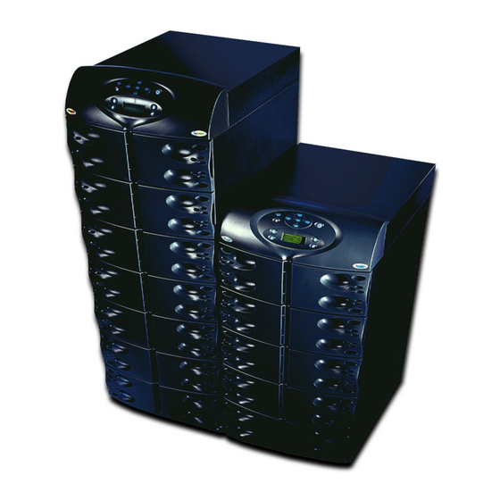
STANDARD COMPONENTS: SYSTEM DESCRIPTION § Power Modules – for power conditioning The Liebert Nfinity Power System is a modular UPS intended for use with workstations, servers, § Battery Modules – for back-up power network, telecom or other sensitive electronic §... -
Page 8: Modes Of Operation
Modes of Operation The Nfinity UPS is designed to operate as a true Recharge Mode on-line system in the following modes: When AC mains is restored, the unit will then Normal Mode automatically recharge the battery modules until The Power Module’s power factor correction they are fully charged. -
Page 9: Major Components
Unit Frame Nfinity’s frame houses all of the other system components. Looking at the front of Nfinity, one will see a series of plastic bezels. By grasping these bezels from the side and pulling out, you will remove the bezel to reveal the Battery / Power Module bays. -
Page 10: User Interface Module
User Interface Module The User Interface Module is the primary source of communication between the UPS and the user. From the interface, the user can: § View the status of the UPS § Custom configure the system § Review the event log to assist with troubleshooting §... -
Page 11: Power Module
Battery Module The Power Module maintains the condition of The Battery Modules provide back-up power in power in the Nfinity UPS. Each module is an the event of input mains failure. Each module independent 4 kVA unit, consisting of a power... -
Page 12: Installation
Installation Preparation Unloading Cable Installation Communications... -
Page 13: Required Setup Equipment
Upon receiving the UPS, examine the packaging to the table below for size and fully populated for any signs of mishandling or damage. If any weight considerations: damage is noted, call your local Liebert Model Max Weight kg H x W x D mm representative and/or notify your carrier. -
Page 14: Unloading The Ups
Unloading Unloading the UPS CAUTION: This UPS is very heavy (see weight on previous page). At least two people should be present to unload it off of the pallet. 1. Once the UPS is near the desired operating location, remove the cardboard cover. 3. -
Page 15: Stationary Mounting
Stationary Mounting Additional stability can be added by bolting the 5. Once the UPS is in its desired location, mounting brackets (used in shipping) to the adjust the leveling feet to secure its position. floor. For greater stability, use a higher-grade bolt. Refer to the dimensions below when drilling holes for stationary mounting. -
Page 16: Wiring Preparation
Cable Installation Power Cable Installation Wiring Preparation Refer to the charts below when selecting cables: WARNING: 8 Bay Power Cable and Protection Ratings Please read this section 220V 230V 240V thoroughly before attempting to install wiring to Max Input this unit. 60 A 60 A 60 A... -
Page 17: Input Wiring (Tb1)
Using a torque wrench, turn the screws clockwise until tightened to the proper torque value. Note the Neutral / Earth jumper on the terminal above. Transformer Models The Nfinity UPS contains an isolation transformer that generates neutral conductor for the connected equipment. -
Page 18: Repo Switch
REPO Switch CAUTION: To maintain safety (SELV) Nfinity is equipped with a Remote Emergency barriers and electromagnetic compatibility Power Off (REPO) Switch. Only connect SELV signal cables should be segregated and run circuits to REPO connector. separately from power cables. -
Page 19: Com Ports
Communication COM Ports Nfinity is able to communicate through multiple communication ports simultaneously. Only use Liebert provided communication cards. Only connect SELV circuits when connecting to any communication port. Intellislot™ Ports Pin Assignment The following communication cards may be used with Nfinity: COM 1 –... -
Page 20: Operating Instructions
Operating Instructions Controls and Indicators Operating Procedures Main Menu... -
Page 21: Controls And Indicators
It consists of a series of Status LED’s, a 4 line by 20 character LCD display window, and buttons for navigation (as displayed above). Buttons LEDs Refer to the legend below in order to properly Refer to the legend below to indicate occurrence navigate the Nfinity User Interface. when an LED is lit. -
Page 22: Status Led Modes
Status LED Modes LED Off LED On LED Flashing UPS is Off or Initializing UPS On, Utility Good and Output Off UPS On, Utility Good and Output On (Normal Operation) UPS On, Utility Bad and Output On (On Battery Operation) UPS On, Utility Bad, and Output Off UPS in Bypass Operation (Manual or Automatic) -
Page 23: Navigating The Menu
Navigating the Menu In order to review or change any settings on the UPS, it must be navigated using the buttons seen on the previous page. Because some menus contain more than four rows information, you may see an arrow on the display pointing up or down (as shown below) –... -
Page 24: Operating Procedures
Operating Procedures Start-up and Initialization Manual Transfer to Bypass Follow these steps in order to start up the UPS. In the event of a UPS overload or failure, the UPS will transfer to bypass via its automatic 1. Ensure the manual bypass switch is in UPS bypass switch. - Page 25 Main Menu After initialization, the button will take you to the main menu. From here you may check on the status of the UPS, review the event and alarm log, configure your UPS, and even receive instructions on replacing modules. The main menu is divided into five sub-menus as shown below: Use the buttons to select the desired menu item and press to access the appropriate sub-menu.
-
Page 26: Ups Status Screen
UPS Status Screen From the main menu the user may select UPS Status and press . Once at the UPS Status Screen, the user may access any information on the present condition of the UPS. Note the chart below when reviewing the UPS. -
Page 27: Ups Configuration Screen
UPS Configuration Screen Review Settings Follow this procedure to review your UPS configuration settings. Any underlined text indicates factory default values. -
Page 28: Change Configuration Settings
Change Settings Menu configuration of the Nfinity. It can be up to 7 characters in length. Once set, the password Starting from the Main Menu, locate and press will be required to change the configuration. UPS Configuration. From the UPS Configuration screen, select the Change Settings option. - Page 29 Daylight Savings. Max Load Alarm Set: Allows an alarm to set when Nfinity’s load reaches a specific level. User Settings: From here one can enter the UPS ID or adjust the contrast of the user interface LCD.
- Page 30 Redundant Alarm Set: Sets Alarm to notify External Battery: Sets total amp-hour for user when redundancy is no longer available. external batteries to provide a more accurate runtime remaining value on the LCD display and through communications. UPS Test: Allows user to test the Batteries, LED’s, LCD, or Alarm.
- Page 31 Frequency Slew Rate: Sets the rate of change of frequency through the sync range window. Bypass Alarm Mode: Allows the user to enable/disable alarm, indicating that the bypass is not qualified.
-
Page 32: Event Log
One may open the Event Log from the main menu. By accessing the Event Log, the user Below is a list of possible events / alarms. may scroll through the Nfinity’s past 255 Occurrence Event Alarm occurrences in chronological order by pressing ü... - Page 33 Module Replacement The user interface also supplies instructions for removing and replacing modules. From the main menu, access the module replacement screen and select the type of module. Refer to the screens below for reference: For more details on module replacement, consult the troubleshooting section of this user manual.
-
Page 34: Troubleshooting
Troubleshooting Alarm Messages Module LED Indication Module Replacement... -
Page 35: Alarm Messages
A list of possible alarm messages is displayed below. If you encounter one of these or other alarm messages and are unsure of the corrective action to take, please contact a qualified Liebert representative at the number listed in the back of this manual. -
Page 36: Module Led Indication
Module LED Indication On every Battery, Power or Control Module are two LEDs to help inform the user of the module status. Refer to the chart below: Status LED Fault LED Module Status (Green) ( Amber) Module not inserted into frame. System is OFF. -
Page 37: Module Replacement
Do Not remove more than one responsible way that complies with local module at a time. Failure to do so codes / regulations or return to Liebert for may cause unit to tip over and cause serious injury. proper disposal. -
Page 38: Replacing Modules
Replacing Modules Replacing the User Interface 1. Lift off user interface and set it on top of the 1. Lift module to appropriate bay, resting end UPS frame. of module on bay shelf. Use caution not to rest the module on the lower bezel cover. 2. -
Page 39: Maintenance
Maintenance Proper Care Scheduled Maintenance Replacing Fan Filters... -
Page 40: Proper Care
Tranformer models only Keeping your Liebert Nfinity UPS operating properly is imperative to optimal performance Nfinity’s intake fans contain filters that will need and life of the unit. It is recommended that a to be replaced / cleaned periodically, depending certified technician perform preventive and on the surrounding environment. - Page 41 Reference Specifications Battery Run Times Warranty Technical Support...
-
Page 42: Specifications
Specifications General & Environmental Units Configuration Unit Rating 11.2 Conducted and Radiated EMC Levels EN 50091-2 Class A Compliant Safety Standards EN50091-1-1, CE, Low Voltage Directive Compliant Immunity Standards EN61000 4-2,3,4,5,6 Mechanical Units 8 Bay 12 Bay Dimensions: Width 508.0 508.0 Depth 711.2... -
Page 43: Battery Run Times
Battery Run Times 8 Bay Frame Internal (minutes) Quantity of Battery Modules Quantity of External Battery Cabinets with Charger Load Load Watts 12,000 8,400 11,500 8,050 11,000 7,700 10,500 7,350 10,000 7,000 9,500 6,650 9,000 6,300 8,500 5,950 8,000 5,600 7,500 5,250 7,000... - Page 44 Battery Run Times 12 Bay Frame Internal (minutes) Quantity of Battery Modules Quantity of External Battery Cabinets with Charger Load Load Watts 10 11 16,000 11,200 10 12 16 19 15,500 10,850 10 13 17 20 15,000 10,500 11 14 18 20 14,500 10,150 11 14 19 21...
-
Page 45: Warranty
(4) to six (6) months when not in use. If the UPS fails to conform to the above warranty within the two-year warranty period, Liebert will repair or replace the UPS, at Liebert's option. Repairs or replacements are warranted for the remainder of the original warranty period. - Page 46 Specifications subject to conditioning from 1.5 to 60 tons. change without notice. Power conditioning and UPS with power ranges from 250 VA to more than 1000 kVA. ® Liebert and the Liebert logo are registered Integrated systems that provide both trademarks of Liebert Corporation.
Need help?
Do you have a question about the Nfinity and is the answer not in the manual?
Questions and answers