Table of Contents
Advertisement
Quick Links
Advertisement
Table of Contents
Troubleshooting

Related Manuals for Xantrex PROSINE 2.0


Summary of Contents for Xantrex PROSINE 2.0
- Page 1 User’s Manual...
- Page 2 Xantrex International Xantrex Technology Inc. is the world’s leading supplier of advanced power electronics with products from 50 watts to 1 megawatt in size for commercial, residential, and recreational markets, as well as distributed and renewable energy markets. The Company was formed by the merger of US-based Trace holdings LLC and Canadian-based Xantrex Technology Inc.
- Page 3 User’s Manual...
-
Page 4: Information About Your System
2.0 I •C ’ SINE NVERTER HARGER ANUAL Information About Your System When you first open the PROsine 2.0 Inverter•Charger package, be sure to record the following: ❐ ____________________________________ Model Number (on DC end) ❐ ____________________________________ Serial Number (on DC end) ❐... -
Page 5: Default Values For Prosine 2.0 System
Default Values for PROsine 2.0 System Table 1 lists the default settings for the PROsine 2.0 system. Record your settings in the right-hand column after you have configured the inverter•charger. This information will be valuable if you need to reconfigure your system or call Xantrex Customer Service. - Page 6 2.0 I •C ’ SINE NVERTER HARGER ANUAL Table 1 Default Values: Inverter•Charger Item Default Value Your Settings Adjustable From the Configure Battery Menu NOTE Settings below are for Battery Type = Generic Gel. Battery Size 200Ah Default Battery Temperature Warm Battery Type Generic Gel...
-
Page 7: Table Of Contents
Information About Your System ........Default Values for PROsine 2.0 System...... - Page 8 2.0 I •C ’ SINE NVERTER HARGER ANUAL Section 3. Installation Safety Instructions ..........Installation Codes .
- Page 9 ABLE OF ONTENTS Section 5. Operation Part 1: System Startup Check ........Part 2: Operating Considerations .
- Page 10 2.0 I •C ’ SINE NVERTER HARGER ANUAL Part 3: Configuring a Series System........Part 4: Series System Startup Test .
- Page 11 PROsine 2.0 Charge Algorithms ........125...
- Page 12 2.0 I •C ’ SINE NVERTER HARGER ANUAL 445-0089-01-01...
- Page 13 List of Tables Table Title Table 1 Default Values: Inverter•Charger....... iii Table 1 Required AC Wire Size vs Breaker Rating .
- Page 14 2.0 I •C ’ SINE NVERTER HARGER ANUAL 445-0089-01-01...
-
Page 15: List Of Figures
Title PROsine 2.0 Materials as Shipped ......AC End View (Blank Panel Option) ...... - Page 16 2.0 I •C ’ SINE NVERTER HARGER ANUAL 445-0089-01-01...
-
Page 17: Important Safety Instructions
MPORTANT AFETY NSTRUCTIONS WARNING This manual contains important safety and operating instructions as prescribed by UL and CSA specifications for inverter•chargers used in residential, RV, and marine applications. ® Before you install and use your PROsine 2.0 Inverter•Charger, be sure to read and save these safety instructions. -
Page 18: Explosive Gas Precautions
2.0 I •C ’ SINE NVERTER HARGER ANUAL 9. The inverter•charger must be provided with an equipment-grounding conductor connected to the AC input ground terminal. Grounding and all other wiring must comply with local codes and ordinances. 10. For marine applications in the United States, external connections to the inverter•charger shall comply with the United States Coast Guard Electrical Regulations (33CFR183, Sub part 1). - Page 19 8. Remove personal metal items such as rings, bracelets, necklaces, and watches when working with lead-acid batteries. Lead-acid batteries produce a short-circuit current high enough to weld a ring or the like to metal, and thus cause a severe burn. 9.
-
Page 20: Materials List
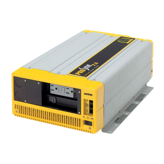
ATERIALS ® Your PROsine 2.0 Inverter•Charger package includes the items listed below. Figure 1 PROsine 2.0 Inverter•Charger 1 Display panel 1 Communications cable (70ft; 21m) 1 Battery temperature sensor with a 25ft (8m) cable 2 DC terminal covers 1 User’s Manual 1 Quick Installation Guide (includes inverter•charger mounting template) -
Page 21: Prosine 2.0 Materials As Shipped
PROsine 2.0 Materials as Shipped NOTE For Marine Installations For marine installations, you must attach the ABYC Warning label in a conspicuous location on the AC load panel. The Warning label is supplied with your PROsine 2.0 Inverter•Charger and is illustrated below: 445-0089-01-01... -
Page 22: Warranty
2.0 I •C ’ SINE NVERTER HARGER ANUAL ARRANTY What does this warranty cover? Xantrex manufactures its products from parts and components that are new or equivalent to new, in accordance with industry-standard practices. This warranty covers any defects in workmanship or materials. -
Page 23: Return Material Authorization Policy
Return Material Authorization Policy You must obtain a Return Material Authorization (RMA) number from Xantrex before returning a product directly to Xantrex. Products returned without an RMA number or shipped collect will be refused. When you contact Xantrex to obtain service, be prepared to supply the serial number of your product and its date of purchase as well as information about the installation or use of the unit. -
Page 24: Contents & Organization Of This Manual
ONTENTS RGANIZATION OF ANUAL This manual is a complete guide to installing, configuring, using, and troubleshooting the PROsine 2.0 Inverter•Charger and is also a source of valuable reference information. Here’s an overview of the contents. Safety Instructions Read these first! Section 1: Introduction This describes key product functions. -
Page 25: Related Documents
It is a job aid that provides instructions for installing the inverter•charger and its display panel. It also provides a mounting template for the inverter•charger. ❐ PROsine 2.0 Inverter•Charger Display Panel Mounting Template Part Number: 445-0101-01-01: This is provided with your inverter•charger. - Page 26 2.0 I •C ’ SINE NVERTER HARGER ANUAL 445-0089-01-01 xxiv...
-
Page 27: Section 1 Introduction
AC to pass through to your loads and automatically begins to recharge the batteries. Reliable Back-up If utility-supplied power fails, the PROsine 2.0 automatically detects the failure and instantly becomes an independent power source that supplies quality AC to your loads. There’s no interruption in service and no degradation in performance. -
Page 28: The Heart Of A Sophisticated, Independent Power System
ANUAL The Heart of a Sophisticated, Independent Power System . . . Your PROsine 2.0 Inverter•Charger has been designed to be the heart of a sophisticated, independent power system. While the inverter•charger is an extremely “friendly” product to operate, Xantrex wants to ensure that you get the best performance from your system. -
Page 29: Charging
Every battery has a unique charge formula (or “algorithm”) dictated by the manufacturer for optimal performance. The PROsine 2.0 has twenty-one built-in formulas to charge your batteries correctly—and you have the ability to fine tune these formulas to meet the needs of new models or specialized batteries. -
Page 30: Power System Management
❐ The PROsine 2.0 uses a Power Share feature which senses the AC load on the system and gives priority to your AC loads, thereby reducing the charger current to avoid nuisance tripping of the breaker. - Page 31 ECTION NTRODUCTION Auto Restart After Errors The PROsine 2.0 protects itself against numerous conditions (e.g. AC overload or over temperature) by shutting down. You can program the inverter•charger to restart automatically when the cause of the shutdown has corrected itself.
- Page 32 2.0 I •C ’ SINE NVERTER HARGER ANUAL 445-0089-01-01...
-
Page 33: Section 2 Product Orientation
Section 2 Product Orientation This section will familiarize you with the following components of a PROsine 2.0 system: • Inverter•charger features. (Start on page • Display panel features. (Start on page 11.) • Battery temperature sensor. (See page 16.) 445-0089-01-01... -
Page 34: Inverter•Charger Features
Also provides a connection for remote shutdown. See “Step 10: Connecting the Remote Shutdown‚” on page 38 SYNC: Jack for synchronizing a second PROsine 2.0 Inverter•Charger to produce 120/240V split phase AC. For details, Section 7: “Series Operation” page 83 starting on Removable panel. -
Page 35: Ac Panel Options
ECTION RODUCT RIENTATION AC Panel Options The PROsine 2.0 has two AC panel options, each of which includes one 30A hardwire output circuit: • Blank access panel: one hardwire output circuit. See Figure • Panel equipped with 15A GFCI receptacle and one hardwire output circuit. -
Page 36: Inverter•Charger: Dc End
2.0 I •C ’ SINE NVERTER HARGER ANUAL Inverter•Charger: DC End Figure 4 Inverter•Charger: DC End Feature Description Positive DC cabling terminal Negative DC cabling terminal Cooling fan. (For details, see “Fan Operation‚” on page 63 Screw holes for mounting accessory modules Chassis ground lug. -
Page 37: Display Panel Features
ANEL EATURES The display panel lets you monitor and control the PROsine 2.0 system. For convenience, the liquid crystal display (LCD) is backlit and the panel can be configured so an audible tone alerts you to any warnings or system faults that occur. -
Page 38: Display Mode Switch
2.0 I •C ’ SINE NVERTER HARGER ANUAL DISPLAY Mode Switch Switch Position Description Puts the unit in Display mode. Data Display screens are shown so you can monitor system performance. Power continues to be available to the panel so vital data like system errors and warning statuses can be checked. -
Page 39: Charger Switch
ECTION RODUCT RIENTATION CHARGER Switch This switch is active in all Display modes: ON, OFF, CONFIGURE. Switch Position Description ENABLE The charger is enabled and will charge the battery according to the way the unit is configured if shorepower is “good.” DISABLE The charger is off and will consume minimal power. -
Page 40: Lcd Panel
SINE NVERTER HARGER ANUAL LCD Panel The LCD panel lets you monitor the PROsine 2.0 system and change its configuration settings. It operates in two basic modes: Data Display and Configuration. Data Display Mode • In Data Display mode the screens provide information about PROsine 2.0 system performance. -
Page 41: Menu Navigation And Data Selection Buttons
ECTION RODUCT RIENTATION Menu Navigation and Data Selection Buttons When the DISPLAY switch is set to CONFIGURE, the menu navigation and data selection buttons operate as follows: Press This Button ESCAPE • Cancel changes made to data • Back up one menu level MENU Up Back up one menu item MENU Down... -
Page 42: Battery Temperature Sensor
Sensor. Reverse side has peel-off backing and self-adhesive strip so you can attach the sensor to the side of the battery case. Sensor cable (25ft; 8m). Connector. Plugs into the Battery Temp jack on the PROsine 2.0. NOTE: The battery temperature sensor is electrically isolated from the mounting plate. -
Page 43: Section 3 Installation
Section 3 Installation This section gives complete information for installing a PROsine 2.0 Inverter•Charger system. Specifically, this section describes: • Safety instructions and installation codes that must be observed during installation • Installation tools and materials • Appropriate locations and environments for mounting the inverter•charger, display panel, and battery temperature sensor... -
Page 44: Installation Tools And Materials
2.0 I •C ’ SINE NVERTER HARGER ANUAL Installation Tools and Materials You will need the following to install the inverter•charger, display panel, and battery temperature sensor: ❐ Wire stripper ❐ Mounting screws or bolts ❐ #2 Phillips screwdriver ❐ Wrench for DC terminals (1/2 inch or 13mm or adjustable) ❐... -
Page 45: Step 1: Designing The Installation
ECTION NSTALLATION Step 1: Designing the Installation All types of inverter•charger installations share common components, and these are briefly described below. Figure 8 shows these components and their relationship to each other in a typical recreational vehicle or fleet vehicle installation. - Page 46 NOTE Do not connect the output of a single PROsine 2.0 to what is known as a “multi- wire branch circuit”. These are 4-wire circuits consisting of a ground, neutral, and two lines that are 180 degrees out of phase with each other (from a standard 120/ 240V “split phase”...
-
Page 47: Table 1 Required Ac Wire Size Vs Breaker Rating
Table 2 specifies the minimum DC cable size and maximum fuse size for the PROsine 2.0. The DC cables must be copper and must be rated 75°C minimum. Table 2 Required DC Cable and Fuse Size DC Cable Length... -
Page 48: Table 3 Tested Gfci Models
Xantrex test and recommend specific GFCIs. Xantrex has tested the GFCI-protected 15A receptacles listed in Table 3 and found that they function properly when connected to the AC output of the PROsine 2.0. Table 3 Tested GFCI Models Manufacturer Model Number... -
Page 49: Step 2: Choosing A Location For The Inverter•Charger
Step 2: Choosing a Location for the Inverter•Charger WARNING This equipment contains components that tend to produce arcs or sparks. To prevent fire or explosion, do not install the PROsine 2.0 Inverter•Charger in compartments containing batteries or flammable materials or in locations that require ignition-protected equipment. This... -
Page 50: Step 3: Mounting The Inverter•Charger
Figure 9 Approved Mounting Orientations 4. The PROsine 2.0 Quick Installation Guide has a mounting template printed on it. Tape it to the mounting surface and pilot-drill the desired number of mounting holes. Remove the template. 5. Fasten the inverter•charger to the mounting surface. If you are mounting the unit on a wall or bulkhead, use #12 or #14 pan-head wood or sheet metal screws to secure it to the framing behind the wall or bulkhead. -
Page 51: Step 4: Connecting The Ac Input Wires
ECTION NSTALLATION Step 4: Connecting the AC Input Wires WARNING: Fire, Shock, and Energy Hazards Make sure wiring is disconnected from all electrical sources before handling. All wiring must be done in accordance with local and national electrical wiring codes. Do not connect the output terminals of the inverter•charger to any incoming AC source. -
Page 52: Ac Input Connections
Figure 11 is a cutaway top view of the PROsine 2.0 wiring compartment. It shows one incoming AC cable and its connections to the PROsine 2.0 wires. ➢ ➢ ➢ ➢ To make the AC input connections 1. Run 10AWG 2-conductor-plus-ground cable through one of the cable clamps on the AC end. -
Page 53: Step 5: Configuring The Output Neutral Bonding System
Step 5: Configuring the Output Neutral Bonding System AC Output Neutral-to-Ground Bonding System The PROsine 2.0 Inverter•Charger provides an installer-defeatable system that automatically connects the neutral conductor of the inverter AC output circuit to safety ground (“bonding” it) during inverter operation, and disconnects it (“un-bonding”... -
Page 54: Table 4 Ac Output Neutral-To-Ground Bonding Screw Settings
2.0 I •C ’ SINE NVERTER HARGER ANUAL identified as the one that enables the automatic bonding system, and the other hole defeats it so that the neutral is not bonded by the PROsine in any mode. The PROsine is shipped with the screw in the position that enables the automatic bonding system. -
Page 55: Step 6: Connecting The Ac Output Wires
5. Connect the outgoing AC wires to an AC load panel equipped with circuit breakers. Cutaway view of grounding screw PROsine 2.0 wiring compartment as seen from the top. wire nuts or crimp connections (depending on type of installation) -
Page 56: Connections For Single Hardwire Output With Gfci
Connections for Single Hardwire Output With GFCI Figure 13 is a cutaway top view of the PROsine 2.0 wiring compartment showing one set of outgoing AC wires with the GFCI option. ➢ ➢ ➢ ➢ To make the AC output wiring connections 1. -
Page 57: Step 7: Connecting The Dc Cables
Table 2 on page 21 specifies the minimum DC cable size and maximum fuse size for the PROsine 2.0. Do not route your DC cables through an electrical distribution panel, battery isolator, or other device that will cause additional voltage drops. - Page 58 2.0 I •C ’ SINE NVERTER HARGER ANUAL ➢ ➢ ➢ ➢ To make the DC connections Refer to Figure 1. Cut the cables to the correct length with enough insulation stripped off so you can properly install the type of terminals you will be using. The terminals on the DC end are designed to fit up to 500MCM crimp-on ring terminals (either AMP or ILSCO) or box connectors.
-
Page 59: Dc Grounding
ECTION NSTALLATION Figure 15 DC Cable Connections DC Grounding ➢ ➢ ➢ ➢ To connect the DC ground The Chassis Ground lug on the DC end of the inverter•charger is used to connect the chassis of the inverter•charger to your system’s DC grounding point as required by regulations for some installations. -
Page 60: Step 8: Mounting The Display Panel
2. Tape the mounting template (in the PROsine 2.0 Inverter•Charger package) to the mounting surface and mark the locations of the mounting holes and the area to be cut away. -
Page 61: Step 9: Connecting The Battery Temperature Sensor
ECTION NSTALLATION Step 9: Connecting the Battery Temperature Sensor Mounting Options You can mount the battery temperature sensor (BTS) in one of two ways: • Mounting the sensor to the negative battery post allows the internal battery temperature to be sensed and provides the most accurate results. •... -
Page 62: Mounting To The Side Of The Battery Case
2.0 I •C ’ SINE NVERTER HARGER ANUAL 2. Switch off all devices operating from the battery, or open the battery switch, if present, to disconnect the battery. 3. If the charger has been operating, wait ten minutes for any explosive battery gasses to dissipate. - Page 63 ECTION NSTALLATION The surface where the sensor is to be mounted must be flat and free from reinforcing ribs or other raised features. As well, this surface must be in direct internal contact with battery electrolyte, so do not install the sensor on a side near the top of the battery or on the battery’s top surface.
-
Page 64: Step 10: Connecting The Remote Shutdown
2.0 I •C ’ SINE NVERTER HARGER ANUAL Step 10: Connecting the Remote Shutdown WARNING: Shock Hazard This step should only be completed by qualified installers or technicians who have a knowledge of DC circuits. Connect only to an isolated Class 2 extra-low voltage power source as described below. -
Page 65: Next Steps
ECTION NSTALLATION 6. Plug the cables into the splitter and connect to the PROsine 2.0 as shown Figure The Remote Shutdown feature is now ready for use. For operating information, see “ON/OFF/REMote Control of Inverter•Charger Operation‚” on page Plug into Battery Temp... - Page 66 2.0 I •C ’ SINE NVERTER HARGER ANUAL 445-0089-01-01...
-
Page 67: Section 4 Configuration
Section 4 Configuration This section explains how to configure the PROsine 2.0 Inverter•Charger to best meet your electrical system requirements. It is divided into three parts: • Part 1: General Configuration Information. (See page 42 and following.) Tells you how to enter Configure mode and Installer mode, how to scroll through the configuration screens, and how to change configuration settings. -
Page 68: Part 1: General Configuration Information
ONFIGURATION NFORMATION All changes to the operation of the PROsine 2.0 Inverter•Charger are made via the display panel. The unit must be in Configure mode or Installer-Only mode before you can change system settings. It is essential that you understand the implications of changing User and Installer settings. -
Page 69: Changing Settings
ECTION ONFIGURATION Changing Settings NOTE All configuration settings are stored in the PROsine’s memory and will not be lost even if all power is disconnected. ➢ ➢ ➢ ➢ To change system settings 1. Set the switch to DISPLAY CONFIGURE 2. -
Page 70: Part 2: Configuration Menus And Screens
2.0 I •C ’ SINE NVERTER HARGER ANUAL 2: C ONFIGURATION ENUS AND CREENS Table 5 shows the organization of the configuration menus and screens. The screens are grouped into five menus: ■ Configure PROsine—Basic ■ Configure PROsine–Advanced ■ Configure Display Panel ■... -
Page 72: Part 3: Configuration Options
2.0 I •C ’ SINE NVERTER HARGER ANUAL 3: C ONFIGURATION PTIONS This section gives you information about the options on each configuration menu. Refer to this section when you are changing system settings. The information in this section is arranged as follows: Configure •... -
Page 73: Configure Prosine-Basic Menu
ECTION ONFIGURATION Configure PROsine—Basic Menu Menu Items Access User AC Breaker Size Load Sensing User Equalize User Menu Choices or Information Displayed ■ AC Breaker Size Set the AC breaker size to match the shorepower circuit breaker size to reduce circuit breaker “nuisance” tripping. Values range from 0–30 amps. ■... -
Page 74: Configure Prosine-Advanced Menu
2.0 I •C ’ SINE NVERTER HARGER ANUAL Configure PROsine—Advanced Menu Menu Items Access Load Sensing User Load Sense Power User Load Sense Interval User User Low AC Transfer (V) Low AC Transfer (Hz) User High AC Transfer (V) User High AC Transfer (Hz) User AC Series Mode... - Page 75 AC Series Mode Select Standalone if you are operating a single inverter•charger to produce 120V single phase. If you are installing two PROsine 2.0 inverter•chargers as a 240 split- phase system, set one inverter•charger as Master and the other as Slave.
- Page 76 2.0 I •C ’ SINE NVERTER HARGER ANUAL Auto Restart After Error WARNING If Auto Restart is selected, AC voltage can reappear at the loads without notice after a fault has occurred and cleared. If you select Yes, the inverter•charger will attempt to restart (five attempts) after a fault has occurred.
-
Page 77: Configure Display Panel Menu
ECTION ONFIGURATION Configure Display Panel Menu Menu Items Access User Audible Alarm LCD Backlight Mode User LCD Backlight Brightness User LCD Backlight Timeout User User Temperature (C/F) Menu Choices or Information Displayed This menu lets you change display panel settings to suit your preferences and environment. -
Page 78: Configure Battery Menu
2.0 I •C ’ SINE NVERTER HARGER ANUAL Configure Battery Menu Menu Items Access Battery Size Installer Default Batt Temp User Battery Type Installer View / Change Battery Details: Installer • Battery Temp. Coefficient • Bulk Charge Mode Settings • Max Voltage Installer •... -
Page 79: Battery Size
ECTION ONFIGURATION Menu Choices or Information Displayed WARNING: Risk of Fire or Explosion Incorrect settings can damage or destroy your batteries. When making any battery configuration settings, ensure that the values are correct according to the battery manufacturer’s specifications. Settings should be changed by qualified personnel only. - Page 80 2.0 I •C ’ SINE NVERTER HARGER ANUAL ■ View / Change Battery Details: The screens associated with these menu items display information about the way the inverter•charger will charge the battery. Battery Temp Coefficient This is the relationship between temperature and voltage levels on the battery.
- Page 81 ECTION ONFIGURATION Overcharge Mode Settings: Max Voltage This is the maximum charging voltage for the Overcharge charging stage. Typically the battery will be at this voltage for the duration of this stage. Max Current (%C) The maximum available charging current (in A) as a percentage of battery capacity (in Ah) for the Overcharge charging stage.
-
Page 82: Charger Mode
■ Charger Mode Select Standalone when a single PROsine 2.0 Inverter•Charger is being used to charge a battery. When multiple PROsine 2.0 Inverter•Chargers are charging a single battery bank, the secondary chargers only operate during the Bulk charge phase, and the primary charger finishes charging the battery. - Page 83 ECTION ONFIGURATION 2-step The inverter•charger will only perform the Bulk, Absorption/ Overcharge, and Standby steps. Some battery manufacturers and users believe that batteries should not be Float charged. CVCC Constant Voltage Constant Current mode (also called “Constant Mode”). This mode is not intended as a standalone battery charger. It may be used as a power supply mode but still requires the presence of a battery in the system.
-
Page 84: Diagnostics Menu
2.0 I •C ’ SINE NVERTER HARGER ANUAL Diagnostics Menu Menu Items Access Read-Only PS System Mode View Last 20 PROsine Faults • PROsine Fault #0 Read-Only • — • PROsine Fault #19 View Last 10 Panel Faults • Panel Fault #0 Read-Only •... -
Page 85: Next Steps
ECTION ONFIGURATION ■ View Last 10 Panel Faults The display panel records the last ten faults that have occurred in the display panel. You can view these for diagnostic and troubleshooting purposes. (See “Display Panel Faults” starting on page 80.) ■... - Page 86 2.0 I •C ’ SINE NVERTER HARGER ANUAL 445-0089-01-01...
-
Page 87: Section 5 Operation
Section 5 Operation This section begins with a system startup check that you carry out after installation and configuration to verify that the PROsine 2.0 Inverter•Charger is operating correctly. The section also provides information that will guide you during routine, ongoing operations. -
Page 88: Part 1: System Startup Check
2.0 I •C ’ SINE NVERTER HARGER ANUAL 1: S YSTEM TARTUP HECK WARNING Review the “Important Safety Instructions” page xv before operating the inverter•charger. ➢ ➢ ➢ ➢ To test the charging and inverting functions 1. Close the battery disconnect and turn on the inverter•charger’s ON/OFF/ REM switch. -
Page 89: Part 2: Operating Considerations
ECTION PERATION 2: O PERATING ONSIDERATIONS Fan Operation The internal cooling fan operates for a number of conditions: • One of the internal operating temperatures is greater than 55°C. NOTE This temperature may be caused by heat in the or by high inverter•charger ambient temperature. -
Page 90: Part 3: Operation In Inverter Mode
Operating Limits for Inverter Operation Power Output The continuous output rating for the PROsine 2.0 is 2000 watts or 17 amps @ 120Vac; surge to 4.5kW. It can deliver this power in an ambient (surrounding) temperature that is up to 40°C. Above this temperature, you must reduce the demand or the unit may shut down. -
Page 91: Input Voltage
AC wiring is of sufficient size, and the battery is of sufficient capacity and is fully charged. As with all inverters, the amount of continuous power that the PROsine 2.0 can deliver without overheating is limited by the ambient air temperature. It... -
Page 92: Part 4: Operation In Charger Mode
2.0 I •C ’ SINE NVERTER HARGER ANUAL 4: O PERATION IN HARGER WARNING “Important Safety Instructions‚” on page xv Review the before operating the inverter•charger. During charging, batteries may generate explosive gasses. Thoroughly ventilate the area around the batteries and ensure that there are no sources of flames or sparks in the vicinity. -
Page 93: Operation In Equalization Mode
The PROsine 2.0 delivers a high quality charge so batteries do not need to be equalized as often as may be necessary when a lower quality charger is used. -
Page 94: Operating Limits For Charger Operation
AC power line. Power Share The PROsine 2.0 shares power with AC loads. It senses pass-through current going to AC loads and subtracts this current from 80% of the breaker setting. -
Page 95: Part 5: Display Mode Screens
° 12.0V +10A 22 12.0V +10A Shows the PROsine 2.0’s voltage and current readings from the battery as well as the battery temperature. If the battery temperature sensor is not installed, the screen on the right is displayed. Screen 2 PROsine: AC In 118.0V 5A 58Hz... - Page 96 2.0 I •C ’ SINE NVERTER HARGER ANUAL 445-0089-01-01...
-
Page 97: Section 6. Troubleshooting
Section 6 Troubleshooting WARNING: Shock and Energy Hazards Do not disassemble the PROsine 2.0 Inverter•Charger. It does not contain any user-serviceable parts. Attempting to service the unit yourself could result in an electrical shock or burn. NOTE If you need to obtain service, see... -
Page 98: General Troubleshooting Guidelines
Xantrex. These details should include the following as well as anything else asked for on page • What loads the PROsine 2.0 was running or attempting to run • What the battery condition was at the time (voltage, state of charge, etc.) if known •... -
Page 99: Shutdown / Restart Without Error Message
ECTION ROUBLESHOOTING Shutdown / Restart Without Error Message While inverting, the inverter•charger could shut down for a few seconds and then restart inverting without reporting an error. This has likely been caused by a reset of the internal microprocessor, which was probably caused by a discharged and/or weak battery. -
Page 100: Ac Bad Causes
2.0 I •C ’ SINE NVERTER HARGER ANUAL AC Bad Causes If the input AC is not acceptable according to the configuration values you have set, the AC Bad Cause screen in the Diagnostics menu indicates why. Specific causes are listed in Table 7. -
Page 101: Warning Messages
ECTION ROUBLESHOOTING Warning Messages Warning messages appear on the display panel LCD to alert you to an impending system change. Warnings do not affect operation. • You can retrieve the previous twenty Warning and/or Error messages by placing the unit in Configure mode and then selecting View Last 20 PROsine Faults from the Diagnostics menu. - Page 102 2.0 I •C ’ SINE NVERTER HARGER ANUAL Table 8 Warning Messages Warning Message Details Action Inv Low Batt Vlt Low battery voltage, invert Check battery state of charge and re-charge if mode. necessary. Check for proper DC cable size. Check all connections for tightness.
- Page 103 ECTION ROUBLESHOOTING Table 8 Warning Messages Warning Message Details Action Unit will now Run without panel is enabled. The inverter•charger can provide 120VAC Loss of the display panel or without warning. run w/o Panel damage to its cable will not prevent the inverter•charger from operating.
-
Page 104: Error Messages
2.0 I •C ’ SINE NVERTER HARGER ANUAL Error Messages Error messages indicate that there has been a change in system operation due to a detected condition. • You can retrieve the previous twenty Error messages by placing the unit in Configure mode and then selecting View Last 20 PROsine Faults from the Diagnostics menu. - Page 105 ECTION ROUBLESHOOTING Table 9 Error Messages Error Message Details Action Inv Low Batt Volts Inverter battery voltage low. Check battery state of charge and re-charge if necessary. Check for proper DC cable size. Check all connections for tightness. Inv High Batt Volts Inverter battery voltage high.
-
Page 106: Display Panel Faults
2.0 I •C ’ SINE NVERTER HARGER ANUAL Display Panel Faults A message is displayed for any fault that is detected in the display panel. If a Panel Fault message appears, you can clear it from the screen by pressing any button on the panel. -
Page 107: Inverter Applications
ECTION ROUBLESHOOTING Inverter Applications The i nverter•charger performs differently depending on the AC loads connected to it. If you are having problems with any of your loads, read this section. Resistive Loads These are the loads that the inverter finds the simplest and most efficient to drive. - Page 108 2.0 I •C ’ SINE NVERTER HARGER ANUAL begin. To drive these loads, either a small companion load must be used to bring the inverter out of its search mode, or the inverter may be programmed to remain on by defeating the search mode feature. See the “Configure PROsine—Basic Menu‚”...
-
Page 109: Section 7 Series Operation
Section 7 Series Operation This section provides the following information about installing and operating two PROsine 2.0 Inverter•Chargers in series: • Part 1: Designing a series system. (See page 84.) • Part 2: Installing a series system. (See page 87.) •... -
Page 110: Part 1: Designing A Series System
System Overview Series operation refers to a specific wiring configuration that allows you to connect two PROsine 2.0 Inverter•Chargers in a way that produces two 120V phases which are synchronized to produce 240V. This is commonly referred to as a “120/240Vac split-phase” supply or “240V single-phase with a center-tap neutral”... -
Page 111: Two Inverter•Charger Series Operation System
ECTION ERIES PERATION DC Fuse / disconnect or circuit breaker Battery 1 Ground DC Fuse / disconnect or circuit breaker Battery 2 Ground Solid lines: 2 b a n k sys te m Dashed lines: a d d cro ss- tie ju m p e rs to cre a te a sin g le b a n k syste m . -
Page 112: Ac Input
If this cable becomes damaged or lost, you can replace it with standard 4-conductor telephone cable, but the length must be ten feet or less. NOTE The series sync cable is an option and is not supplied with the PROsine 2.0 Inverter•Charger. Contact Xantrex or your distributor for this part. 445-0089-01-01... -
Page 113: Part 2: Installing A Series System
NSTALLING A ERIES YSTEM WARNING Xantrex Technology recommends that all wiring be completed by a certified technician or electrician to ensure adherence to approved electrical wiring regulations. WARNING: Fire, Shock, and Energy Hazards Make sure wiring is disconnected from all electrical sources before you handle. -
Page 114: Connecting Ac Output Wiring
2.0 I •C ’ SINE NVERTER HARGER ANUAL Connecting AC Output Wiring ➢ ➢ ➢ ➢ To connect each inverter•charger to the load panel 1. Connect 2-conductor-plus-ground cable to the Line 1 PROsine Inverter•Charger’s AC Output line and neutral conductors, and connect the cable’s ground wire to one of the output ground screws on the inverter•charger. -
Page 115: Connecting The Dc Cables
Xantrex recommends that you use batteries of the same type, size, and condition. • Connect each PROsine 2.0 to the battery, making sure the polarity is correct. For DC wiring steps, refer to “Step 7: Connecting the DC Cables” starting on page •... -
Page 116: Installing The Display Panels
2.0 I •C ’ SINE NVERTER HARGER ANUAL Installing the Display Panels • Mount and connect the display panel for each inverter•charger. (For details, see “Step 8: Mounting the Display Panel‚” on page 34.) NOTE Each inverter•charger must have its own panel so you can properly monitor and control the system. -
Page 117: Part 3: Configuring A Series System
ECTION ERIES PERATION 3: C ONFIGURING A ERIES YSTEM Configure each inverter•charger through its display panel. Refer to “Part 2: Configuration Menus and Screens‚” on page 44 for an overview of configuration options. Refer to “Part 3: Configuration Options” page 46 and following for specific configuration items. -
Page 118: Part 4: Series System Startup Test
2.0 I •C ’ SINE NVERTER HARGER ANUAL 4: S ERIES YSTEM TARTUP ➢ ➢ ➢ ➢ To test the system’s inverting and charging functions 1. Apply DC to both inverter•chargers by closing the battery disconnect(s). Remove AC by opening the AC input source breaker. On both inverter•chargers, set the ON/OFF/REM switch to On. -
Page 119: Part 5: Series System Operation
ECTION ERIES PERATION 5: S ERIES YSTEM PERATION Invert Mode The two inverter•chargers will operate strictly as a pair in Invert mode. Before each cycle of AC output, the two units confer over the sync cable to verify that the other unit has no errors and is ready to put out the next cycle. A number of conditions must be met for the pair of inverter•chargers to invert: •... - Page 120 2.0 I •C ’ SINE NVERTER HARGER ANUAL 445-0089-01-01...
-
Page 121: Appendix A Specifications
Appendix A Specifications This appendix contains specifications and performance graphs for the inverter•charger and its display panel. 445-0089-01-01... -
Page 122: Electrical Specifications: Invert Mode
2.0 I •C ’ SINE NVERTER HARGER ANUAL Electrical Specifications: Invert Mode DC Input Operating voltage range 10.0V–16.0V Safe non-operating voltage range 0–18Vdc Nominal current at full load 200A AC Output Output voltage 117Vac Continuous power 2.0kW, 2.0kVA to 40°C max. ambient Surge power 4.5kW for 5s Max short-circuit current... -
Page 123: Environmental Specifications
PPENDIX PECIFICATIONS Charger current derating Automatically reduce charger current as internal ° C, input Vac temperature exceeds 80 approaches low transfer, and ac input current approaches 80% of breaker setting. Efficiency at nominal output Other Battery type settings Gel, Flooded, AGM, Pb-Ca Battery size settings 50–2000 Ahr Charge algorithms... -
Page 124: Inverter Overload Operation
2.0 I •C ’ SINE NVERTER HARGER ANUAL Inverter Overload Operation This graph shows how long the inverter•charger will operate for given output current. Time to Shutdown vs. Current 10000.00 Unit shuts dow n sooner for 1000.00 higher internal heatsink temperature. -
Page 125: Invert Power Derating Vs Ambient Temperature
PPENDIX PECIFICATIONS Invert Power Derating vs Ambient Temperature ° If the unit is in elevated ambient temperature above 40 C, you are required to reduce power draw according to the following chart to maintain regulatory compliance and to avoid over-temperature shutdown. Inverter Output Power vs. -
Page 126: Inverter•Charger Dimensions
2.0 I •C ’ SINE NVERTER HARGER ANUAL Inverter•Charger Dimensions 10 1/2” (267mm) 11 3/8” (289mm) Figure 21 Inverter•Charger Dimensions 445-0089-01-01... -
Page 127: Appendix B Typical System Diagrams
Appendix B Typical System Diagrams Each PROsine 2.0 Inverter•Charger installation is a custom-designed system. The diagrams in this appendix illustrate typical designs for: • Residential backup. (See page 102.) • Marine installations. (See page 103.) For a typical RV or Fleet Vehicle installation, see... -
Page 128: Residential Backup System
2.0 I •C ’ SINE NVERTER HARGER ANUAL Residential Backup System Figure 22 illustrates a typical residential backup system with the following features: 1. AC power supplied by a utility system 2. DC power supplied by a battery bank and protected by a DC fuse in the positive cable 3. -
Page 129: Marine System
PPENDIX YPICAL YSTEM IAGRAMS Marine System Figure 23 illustrates a typical marine system with the following components: 1. AC power supplied from a shorepower connector 2. An AC source panel that includes a Max 30A circuit breaker that supplies the inverter•charger 3. - Page 130 2.0 I •C ’ SINE NVERTER HARGER ANUAL 445-0089-01-01...
-
Page 131: Appendix C Batteries
Temperature Compensation Optimal battery charging voltage is temperature dependent. As the ambient temperature falls, the proper voltage for each charge stage needs to be increased. The Prosine 2.0 battery temperature sensor automatically re-scales charge-voltage settings to compensate for ambient temperatures. -
Page 132: Battery Types
2.0 I •C ’ SINE NVERTER HARGER ANUAL Battery Types For the purpose of this discussion, there are two principal battery types: starting and deep-cycle. There are several different types of battery chemistries including flooded and gel lead-acid, nickel-iron (NiFe), nickel- cadmium (NiCad), alkaline, and gel-cell. -
Page 133: Sealed Gel-Cell
PPENDIX ATTERIES Some systems use the L16 type of battery. These are 6-volt batteries rated at 350Ah and are available from a number of manufacturers. They are 17 inches (43cm) high and weigh up to 130 pounds (60kg) each—which may be troublesome in some installations. -
Page 134: Enclosures
2.0 I •C ’ SINE NVERTER HARGER ANUAL Enclosures Batteries must be protected inside a ventilated enclosure. The enclosure should be ventilated to the outdoors from the highest point to prevent the accumulation of hydrogen gases released in the charging process. An air intake should also be provided at a low point in the enclosure to allow air to enter the enclosure to promote good ventilation. -
Page 135: Battery Bank Sizing
PPENDIX ATTERIES Battery Bank Sizing Just as important as the type of battery selected for use with your PROsine Inverter•Charger is the battery size or capacity. The batteries are the most important part of your system, so Xantrex recommends that you purchase as much battery capacity as possible. -
Page 136: Estimating Battery Requirements
2.0 I •C ’ SINE NVERTER HARGER ANUAL Estimating Battery Requirements To determine the proper battery bank size, you need to compute the number of amp-hours that will be used between charging cycles. When the required amp- hours are known, size the batteries at approximately twice this amount. Doubling the expected amp-hour usage ensures that the batteries will not be overly discharged and extends battery life. -
Page 137: Battery Bank Sizing Example
PPENDIX ATTERIES Battery Bank Sizing Example The following battery sizing example illustrates a typical calculation, assuming an opportunity to charge the batteries every three days: Table 11 Battery Sizing Example Daily watt- hours needed for this (A) Power (B) Operating Time appliance Appliance Consumption... -
Page 138: Table 12 Battery Sizing Worksheet
2.0 I •C ’ SINE NVERTER HARGER ANUAL Battery Bank Sizing Worksheet The following worksheet is a guide to help you determine your battery needs. Be generous in estimating the time for which you will run each of the loads to ensure sufficient battery capacity. -
Page 139: Monthly Battery Maintenance
PPENDIX ATTERIES Monthly Battery Maintenance WARNING Wear appropriate eye protection and rubber gloves when carrying out maintenance activities. WARNING Use caution when working with metal tools around batteries. Do not allow any metal object to contact both battery terminals at the same time. Battery explosion or failure can occur. -
Page 140: Tools
2.0 I •C ’ SINE NVERTER HARGER ANUAL Tools ❐ Ajustable wrench or appropriately sized sockets and ratchet ❐ Adjustable and/or locking pliers ❐ Torque wrench (suggested, not required) ❐ Soft-bristled brush (a discarded toothbrush works fine) ❐ 6 inch scrub brush ❐... - Page 141 PPENDIX ATTERIES acid. If it contacts your skin, it will cause burns unless you rinse it off immediately. Most textiles that are exposed to this corrosive eventually dissolve. The most common cause of battery system failure is loose or corroded battery terminals and cable lugs.
-
Page 142: Cabling & Hook-Up Configurations
2.0 I •C ’ SINE NVERTER HARGER ANUAL Cabling & Hook-up Configurations Several smaller batteries can be connected to create a battery bank of substantial size. You can connect batteries in three ways: in parallel, series, or series–parallel (“cross-tied”). To make a larger battery bank, connect individual batteries with heavy cables. The actual size of the cable depends on whether the batteries are connected in parallel or series. -
Page 143: Series Connection
PPENDIX ATTERIES Series Connection When batteries are connected with the positive terminal of one to the negative terminal of the next, they are connected in series. In a series configuration, the battery bank has the same Ah rating of a single battery, but an overall voltage equal to the sum of the individual batteries. -
Page 144: Series-Parallel And "Cross-Tied" Connections
2.0 I •C ’ SINE NVERTER HARGER ANUAL Series–Parallel and “Cross-Tied” Connections As the name series–parallel implies, both the series and parallel techniques are used in combination. The result is an increase in both the voltage and the capacity of the total battery bank. Cross-tying is used frequently to make a larger, higher voltage battery bank out of several smaller, lower voltage batteries. -
Page 145: Appendix D Battery Charging Reference
Appendix D Battery Charging Reference This appendix provides information about the following aspects of battery charging: • Three-stage charging. (See page 120.) • Two-stage charging. (See page 122.) • Charging times. (See page 123.) • Charging algorithms and charge types. (See Table 14 on page 125 Table 15 on page 126.) -
Page 146: Multi-Stage Charging
Three-Stage Charging Profile Modern lead-acid batteries last longer and charge faster if they are charged in a particular sequence known as a three-stage charge. The PROsine 2.0 Inverter•Charger implements the three-stage charging process, plus a user- triggered equalization charge. The charging current and voltage delivered to the battery vary depending on: •... -
Page 147: Bulk Charge
PPENDIX ATTERY HARGING EFERENCE Bulk Charge In the first stage, known as the bulk charge, the PROsine Inverter•Charger delivers the maximum current allowable given the settings noted above: that is, battery type and temperature, maximum AC input setting, and battery bank size. -
Page 148: Equalization Charge
In a two-step charge, the charger finishes Absorption but does not go to Float mode because some battery manufacturers advise against floating their batteries. The PROsine 2.0 goes into a monitoring mode instead where the inverter•charger monitors the batteries but does not charge or float them. In this mode, the PROsine 2.0 will not supply current to power loads. -
Page 149: Battery Charging Times
PPENDIX ATTERY HARGING EFERENCE Battery Charging Times Charging time depends on the capacity of your battery bank and on how deeply it is discharged. The following equation gives an approximate charging time: Charging Time = CAP x DOD CC x 80 where: Charging Time = Battery recharge time in hours CAP = Battery capacity in amp hours... -
Page 150: Battery Charging And Equalization Guide
Table 13 provides general charging information about standard battery types. This information will help you use your PROsine 2.0 to give your batteries the best charge. Note in particular, the information in the “Equalization” column. Table 13 Battery Charging and Equalization Guide—General... -
Page 151: Prosine 2.0 Charge Algorithms
PPENDIX ATTERY HARGING EFERENCE PROsine 2.0 Charge Algorithms Table 14 summarizes the voltage and current setpoints for the charging algorithms. These voltage setpoints are applied for a battery temperature of 20°C. To determine the voltage setpoints at other temperatures, apply the temperature coefficient as follows: ×... -
Page 152: Battery Type-Charge Algorithm Guide
2.0 I •C ’ SINE NVERTER HARGER ANUAL Battery Type—Charge Algorithm Guide Use the information in the following table to match your battery type with the appropriate Charge Algorithm and Charger Type. Table 15 Battery Type – Charge Algorithm Guide If you have this kind of battery Select And set... - Page 153 PPENDIX ATTERY HARGING EFERENCE Keystone Solid Energy (Gel) 3 Step Metra Electronic - Tsunami, Normal 3 Step Optima Blue Top 3 Step Optima Red Top 3 Step Optima Yellow Top 3 Step Rolls Deep Cycle by Surrette 3 Step Sears Canada, Marine by Delco 3 Step Sears Canada, Marine Flooded by Exide 3 Step...
- Page 154 2.0 I •C ’ SINE NVERTER HARGER ANUAL 445-0089-01-01...
-
Page 155: Index
NDEX Symbols batteries AGM (absorbed glass mat) %C, explanation of alkaline amp-hour capacity best environment and location for absorption charge charging times ABYC compliance dead batteries, charging ABYC Warning label deep-cycle AC Bad Cause depth of discharge AC Breaker Size dry-cell xvii AC cabling... - Page 156 NDEX battery monitor Clear Errors in PROsine battery requirements, estimating clocks battery reserve capacity accuracy of battery size, minimum recommended battery operated Battery Temp jack coffee pots battery temperature compressors battery temperature sensor computers attaching to battery terminal configuration attaching to side of battery Configure Battery menu cable Configure Display Panel menu...
- Page 157 PROsine 2.0 system equalize, enabling / disabling recording your settings Error messages depth of discharge (DOD) Escape button Diagnostics menu estimating battery requirements...
- Page 158 NDEX input voltage range on display panel installation Sync, illustrated battery temperature sensor choosing a location codes kill switch. See remote shutdown. connecting AC input wires KKK compliance connecting AC output wires knockouts connecting DC cables connecting remote shutdown designing an installation LCD panel materials backlight...
- Page 159 NDEX Configure PROsine—Basic PROsine Display Panel faults Diagnostics PROsine Error navigating PROsine Warning selecting data pumps microwave purchase date model number motor loads motors Quick Installation Guide xxiii capacitor start Quick Reference Guide xxiii induction running current starting current radios (AM) universal recreational vehicles, DC grounding mounting environment...
- Page 160 NDEX Invert mode single inverter•charger series sync cable system diagrams installing fleet vehicle marine to order xviii residential backup series sync connection series system series operation battery bank(s) system startup check battery temperature sensors series operation components single inverter•charger configuring designing display panels illustrated...
- Page 161 NDEX period of coverage terms website, Xantrex xxiii wire sizes, AC wiring enclosure, DC wiring, separation of AC and DC Xantrex email xviii fax number xviii phone number xviii website xxiii 445-0089-01-01...
- Page 162 NDEX 445-0089-01-01...
- Page 164 Tel: 1-800-670-0707 (Toll free) Tel: 1-360-925-5097 (Direct) Fax: 1-360-925-5143 Web: www.xantrex.com Made in China Email: customerservice@xantrex.com 445-0089-01-01...
Need help?
Do you have a question about the PROSINE 2.0 and is the answer not in the manual?
Questions and answers