Table of Contents
Advertisement
Quick Links
TM
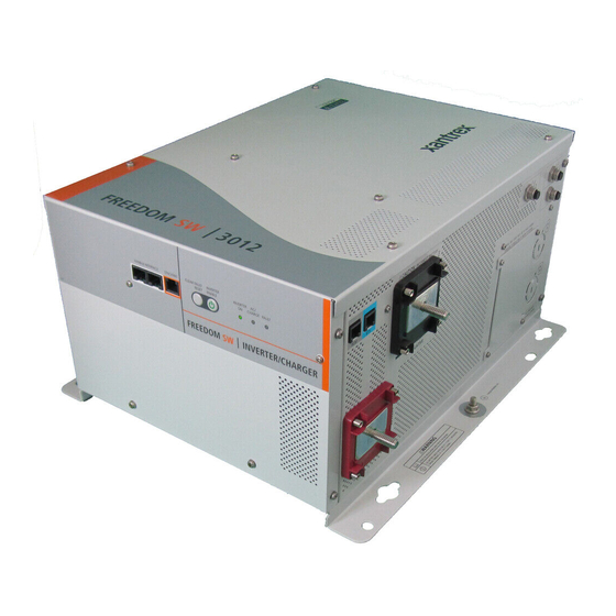
Freedom SW 3012 shown.
Freedom SW
Sine Wave Inverter/Chargers
FAU
LT
IN
ER
AC
ING
ERT
WA
RN
INV
AB
LED
G
RT
ER
EN
AR
GIN
VE
LE
CH
IN
AB
N
UL
T
EN
GE
PPO
RT
R FA
T
SU
EA
RE
SE
CL
CL
EA
R FA
RE
UL
T
SE
T
IN
VE
EN
RT
AB
LE
ER
INV
EN
ER
AB
TER
LED
AC
IN
SU
GE
N
PPO
RT CH
AR
GIN
G
FA
UL
T
WA
RN
ING
TM
Owner's Guide
Model Numbers
815-3012, 815-3024
815-2012, 815-2024
™
Advertisement
Table of Contents
Troubleshooting

Related Manuals for Xantrex Freedom SW Series


Summary of Contents for Xantrex Freedom SW Series
- Page 1 R FA R FA RT CH Owner’s Guide Freedom SW 3012 shown. Freedom SW Model Numbers 815-3012, 815-3024 815-2012, 815-2024 Sine Wave Inverter/Chargers ™...
-
Page 3: Information About Your System
_________________________________ ACCURACY CANNOT BE GUARANTEED PPROVED CONTENT IS CONTAINED WITH THE NGLISH LANGUAGE VERSION WHICH IS POSTED AT WWW XANTREX To view, download, or print the latest revision, visit the website shown under Contact Document Part Number Information. 97-0019-01-01 Date and Revision... - Page 4 About This Guide Purpose Related Information The purpose of this Owner’s Guide is to provide explanations and You can find more information about Xantrex-branded products and procedures for operating, troubleshooting, and maintaining the Freedom services at www.xantrex.com. SW Inverter/Charger. For information on product installation, please refer to the Freedom SW Installation Guide (Document Part Number: 97-0020-01-01).
-
Page 5: Important Safety Instructions
Important Safety Instructions IMPORTANT: R ’ EAD AND SAVE THIS WNER UIDE FOR FUTURE REFERENCE DANGER indicates an imminently hazardous situation, which, if not avoided, will result in death or serious injury. This chapter contains important safety and installation instructions for the Freedom SW Inverter/Charger (Freedom SW). -
Page 6: Safety Information
Safety Information ELECTRICAL SHOCK HAZARD FIRE AND BURN HAZARD • Do not expose the Freedom SW to rain, snow, spray, or bilge water. • Do not cover or obstruct the air intake vent openings and/or install in This inverter/charger is designed for marine applications only when a zero-clearance compartment. -
Page 7: Precautions When Working With Batteries
NOTES: Always have someone within range of your voice or close enough to come to your aid when you work near a lead-acid battery. Follow these instructions and those published by the battery manufacturer and the manufacturer of any equipment you intend to use Always have plenty of fresh water and soap nearby in case battery acid in the vicinity of the battery. - Page 8 Precautions When Preparing to Charge Precautions When Placing the Inverter/Charger RISK OF DAMAGE TO THE INVERTER/CHARGER EXPOSURE TO CHEMICALS AND GASES HAZARD • Never allow battery acid to drip on the inverter/charger when reading • Make sure the area around the battery is well ventilated. gravity, or filling battery.
- Page 9 Regulatory FCC Information to the User The Freedom SW Inverter/Charger is certified to appropriate US and This equipment has been tested and found to comply with the limits for a Canadian standards. For more information see “Regulatory Approvals” on Class B digital device, pursuant to part 15 of the FCC Rules. These limits the Specifications section in the Owner’s Guide.
- Page 10 Electronic equipment such as the circuit boards, connectors, and fuses can be broken down and recycled by specialized recycling companies whose goal is to avoid having these components end up in the landfill. For more information on disposal, contact Xantrex. viii Freedom SW Owner’s Guide...
-
Page 11: Table Of Contents
Contents Important Safety Instructions ..................iii Introduction . - Page 12 Operating the Freedom SW with the SCP................23 Using the Xanbus SCP .
- Page 13 ACIn Settings ..................64 Gen Support .
-
Page 15: Introduction
Introduction Congratulations on your purchase of the Freedom SW Inverter/Charger (Freedom SW). The Freedom SW has been designed to give you premium power, ease of use, and outstanding reliability. Please read this chapter to familiarize yourself with the main performance and protection features of the Freedom SW. 97-0019-01-01... -
Page 16: Materials List
Two sets of 5/16”-18 nuts and washers for the DC Freedom SW 3012 shown terminals NOTE: If any of the items are missing, contact customer service or any authorized Xantrex dealer for replacement. See Xanbus network “About This Guide” on page ii. terminators... -
Page 17: Key Features
Introduction • Surge capacity to start difficult loads like refrigerators or Key Features A/C compressors. The Freedom SW Inverter/Charger is a true sine wave • Power factor-corrected (PFC) input minimizes AC input current inverter/charger that can be used for mobile, marine and required for charging, increasing AC pass-through capacity. -
Page 18: Key Features Explained
Introduction Key Features Explained even if the battery voltage is very low (5 volts for Freedom SW 2012 / 3012 units and 12 volts for Freedom SW 2024 / Built-in Charge Formulas For the unit to perform at the 3024 units). highest level, the batteries must be charged correctly. -
Page 19: Stacking
Introduction Stacking Stack Charging Supports stacking of two inverter/chargers to increase Two Freedom SWs synchronize charging stages to ensure capacity. This also requires the installer to select a Master and efficient charging of the battery bank. When a single unit Slave in order for the inverters to stack. -
Page 20: Generator Assist
Introduction Basic Protection Features Generator Assist The Freedom SW Series of inverter/chargers can operate in The Freedom SW has the following protection features: tandem with a generator (or shore power) to temporarily • Over temperature shutdown for critical components such... -
Page 21: System Components
System Components Xanbus System The Freedom SW uses Xanbus, a network communications protocol developed to communicate the Freedom SW’s The Xanbus system includes the Freedom SW and other settings and activity to other Xanbus-enabled devices. Xanbus-enabled devices. The Freedom SW is the device in a You can configure and monitor the Freedom SW and every Xanbus system that typically provides network power—500 Xanbus-enabled device in the system using an optional... - Page 22 • Controlled by software that eliminates analog signalling errors. • Less susceptible to interference and line loss. • Upgradable through new software releases. For detailed instructions and a complete list of Xanbus- enabled devices, visit www.xantrex.com. Freedom SW Owner’s Guide...
-
Page 23: Xanbus-Enabled Products And Accessories
System Components Xanbus-enabled Products and Accessories Product/Accessory (Shown above) Product Number/s Freedom Freedom Sequence Intelligent Power Manager 809-0912 / 809-0913 Sequence Xanbus System Control Panel (SCP) 809-0921 Xanbus Automatic Generator Start (AGS) 809-0915 3-ft network cable (0.9 m) 809-0935 25-ft network cable (7.6 m) 809-0940 75-ft network cable (22.9 m) 809-0942... -
Page 24: Freedom Sw Inverter/Charger Mechanical Features
Freedom SW Inverter/Charger Mechanical Features Front Panel Compartment Controls and Side Status LEDs A BL U LT C LE C LE U LT V ER A BL T CH AR Cooling Fans DC Terminal Side and Ground Terminal Stud Figure 3 Freedom SW Front and Side Panels (Freedom SW 3012 shown) Freedom SW Owner’s Guide... -
Page 25: Freedom Sw Front And Side Panels
Freedom SW Inverter/Charger Mechanical Features Freedom SW Front and Side Panels Before you begin to operate the Freedom SW, review the front panel features shown in Figure 4 and described in the next table. A detailed view of the LEDs and buttons on the front panel is shown in Figure 5 and described in the table next to it. - Page 26 Freedom SW Inverter/Charger Mechanical Features Item Description DC terminals. AC wiring compartment access panel with compartment cover on. FAULT LED turns on solid if a fault condition occurs and flashes intermittently when a WARNING condition is active. When AC is present and qualified, the AC IN LED will R FA turn on solid indicating also that AC is passing through.
- Page 27 Freedom SW Inverter/Charger Mechanical Features Item Description CLEAR FAULT RESET button is used to clear any active faults if pressed momentarily. If held down for more than three seconds, the unit will reset (reboot) itself. STACKING port is used to connect two inverter/ chargers together for stacked operation.
-
Page 28: Freedom Sw Ac And Dc Side Panels
Freedom SW Inverter/Charger Mechanical Features Freedom SW AC and DC Side Panels Item Description Remote (REM) jack provides connection for the The DC side of the Freedom SW has the equipment ground Freedom Sine Wave remote panel. lug, the positive (+) battery terminal, and the negative (-) Battery temperature sensor (BTS) jack provides battery terminal plus the remote network com port and battery connection for the battery temperature sensor (supplied). -
Page 29: Freedom Sw Supplied Accessories
Freedom SW Inverter/Charger Mechanical Features Freedom SW Supplied Accessories Item Description Two DC terminal covers are supplied to prevent accidental contact with the DC cable connectors after installation. The red cover is for the positive cabling terminal, and the black cover is for the negative cabling terminal. BTS, the Battery Temperature Sensor consists of: Connector plugs into the BTS jack on the Freedom SW. -
Page 31: Freedom Inverter/Charger Operation
Freedom Inverter/Charger Operation Start Up Behavior When the Freedom SW is powered up or has been reset, all of Operating mode, the inverter function reverts back to its prior the front panel LEDs turn on and remain on for a minimum of state. -
Page 32: Inverter Operation Using The Front Panel
Freedom Inverter/Charger Operation Inverter Operation Using the Front Panel To operate the inverter with the System Control Panel, IMPORTANT: Review the “Important Safety Instructions” on page iii refer to “Operating the Freedom SW with the SCP” on before operating the inverter/charger. page 23. - Page 33 Freedom Inverter/Charger Operation Table 1 Front Panel LEDs If any part of this test fails, determine the cause before using the unit. Action (or Status 8. Monitor the Freedom SW Front Panel. Label Color Status Item) AC IN Steady When the Freedom You can run your The indicator LEDs on the front panel show you the Green...
-
Page 34: Operating Limits For Inverter Operation
The Freedom SW series of inverter chargers feature a surge rating of 200% of rated power for five seconds at 25 °C. Operating the inverter/charger in conditions outside of power and temperature limits, however, will result in thermal shutdown and/or significantly decreased performance. -
Page 35: Operating Limits For Charger Operation
Freedom Inverter/Charger Operation Operating Limits for Charger Operation • DC cabling is no longer than the recommended length. Refer to the Freedom SW Sine Wave Inverter/Chargers By default, the maximum charger output current is the rated Installation Guide for this information. charger output current for the particular model. - Page 36 Freedom Inverter/Charger Operation loads and increase the output again when the AC load decreases. The regulatory maximum for continuous AC loads is 80% of the breaker rating (see “AC1 Breaker” on page 50) that the loads are connected to. The Freedom SW senses pass- through current going to the AC load.
-
Page 37: Operating The Freedom Sw With The Scp
Operating the Freedom SW with the SCP This section contains detailed information and procedures for The SCP provides operating, configuration, and monitoring using your Freedom SW in conjunction with the System capability for your Xanbus system. Control Panel (SCP). The SCP: If you’re using the SCP to operate or monitor the status of the •... -
Page 38: Using The Xanbus Scp
Operating the Freedom SW with the SCP Using the Xanbus SCP System Control Panel As shown in Figure 8, the SCP has these important features: Display screen System information is shown on the display The Xanbus System Control Panel (SCP) provides screen with an adjustable backlight. - Page 39 Operating the Freedom SW with the SCP NOTE: All functions on the front panel can also be controlled Item Description from the SCP. AC In/Charge LED indicates that qualified AC is present at the input of an inverter/charger. When the Freedom SW is connected to a qualified AC source like the utility grid or a generator, this LED on the SCP turns on.
- Page 40 Operating the Freedom SW with the SCP Item Description Item Description Screen displays menus, settings, and system Down ( Up) arrow buttons: information. Displays a menu screen title, four lines Scrolls down (up) one line of text. of menu items, and a line that contains small arrows Decreases (increases) a selected value.
-
Page 41: Scp Navigation
Operating the Freedom SW with the SCP SCP Navigation Startup Screen screen. You can view the device Home screen for the Freedom SW and other devices in the system by pressing the up and This screen is shown when the Xanbus SCP first receives down arrows. - Page 42 Operating the Freedom SW with the SCP The System Status screen always features a menu arrow To display the Select Device menu: pointing to the Enter button. Pressing Enter takes you to the ◆ While viewing the System Status screen, press Enter. Select Device menu screen.
-
Page 43: Soft Key Navigation
Operating the Freedom SW with the SCP Soft Key Navigation Soft keys are the objects on the fifth line of the System Status screen. The soft keys have arrows that point to a FSW3012 00: Setup corresponding physical button such as the Enter, Up arrow, Mode Invert Down arrow, and Func buttons. - Page 44 Operating the Freedom SW with the SCP System Status System Status System Status Battery 12.1V -257A 84”F Battery 12.1V -257A 84”F Battery 12.1V -257A 84”F BatLev Invert BatLev Invert BatLev Invert Load 120V Load 120V Load 120V AC In AC In AC In menu EnInv...
-
Page 45: Viewing The Firmware Revision Number
Operating the Freedom SW with the SCP Viewing the Firmware Revision Number You may need to view the firmware revision number (F/W To view the F/W Rev. from the System Status screen: Rev.) of the Freedom SW when troubleshooting the unit with authorized service personnel. -
Page 46: Setting The Time And Date
Operating the Freedom SW with the SCP Setting the Time and Date Using the STBY/ON Fault Clear Button Freedom SW advanced features such as time-stamped events The STBY/ON Fault Clear button has two functions. (faults, warnings, and logged historical data) require that the The STBY/ON Fault Clear is used to clear active faults on system be set to the correct time. -
Page 47: Reading The System Status Screen
Operating the Freedom SW with the SCP Reading the System Status Screen Table 2 System Status Screen The System Status screen displays: Line 1 Label: “System Settings” • Battery-related information (see Line 2) Line 2 Label: Battery Field 1: Total battery current. Negative value if the •... - Page 48 Operating the Freedom SW with the SCP Table 2 System Status Screen Line 5 Label: AC In Field 9: AC input voltage at AC In terminals of the inverter/charger. Voltage is reported by the Master unit if more than one inverter/charger is installed. Field 10: Master current Field 11: Sum of all L1 AC input current from both...
-
Page 49: Reading The Freedom Sw Device Setup Screen
Operating the Freedom SW with the SCP Reading the Freedom SW Device Setup Screen The Freedom SW Device Setup menu screen displays real- To view the Freedom SW Setup menu screen: time operational data (status information) specific to the 1. On the Select Device screen, press the Down arrow Freedom SW. - Page 50 Operating the Freedom SW with the SCP Table 3 Device Setup Screen Status Information Complete list Freedom SW Device Line 1 Label: “FSW3012 00: Setup” Setup fields. Line 2 Label: Mode FSW3012 00: Setup FSW3012 00: Setup Line 1 Line 2 Mode Invert Mode...
- Page 51 Operating the Freedom SW with the SCP Table 3 Device Setup Screen Status Information Table 4 Freedom SW Device Setup Screen Operating States (Modes) Line 5 Label: AC In State (Mode) Displayed When... Field 8: AC input voltage at AC In terminals of The Freedom SW is determining if AC input is Qualifying the inverter/charger.
- Page 52 Operating the Freedom SW with the SCP Table 4 Freedom SW Device Setup Screen Operating States (Modes) State (Mode) Displayed When... State (Mode) Displayed When... There is AC input from the generator, and the Gen Support One Freedom SW unit has completed the ABS Finish Freedom SW is supporting the generator by absorption stage and is waiting for other...
-
Page 53: Configuring The Freedom Sw Using The Scp
Configuring the Freedom SW using the SCP This section contains information about all configurable settings and procedures for the Freedom SW. Power Up It provides information on using the SCP to configure the Startup Screen Freedom SW settings for optimal performance. Please refer to the Xanbus System Control Panel Owner’s Guide for detailed System Status information on how to use the SCP. -
Page 54: Viewing The System Status Screen
Configuring the Freedom SW using the SCP Viewing the System Status Screen Viewing the Select Device Menu The System Status screen displays system activity. The The Select Device menu is where you can view a list of all the information appearing on the System screen varies with the Xanbus-enabled devices in your power system. -
Page 55: Selecting The Freedom Sw From The Select Device Menu
Configuring the Freedom SW using the SCP Selecting the Freedom SW from the Select You can view and change Freedom SW settings from the Setup menu screen. The Basic Settings and Advanced Device Menu Settings bring up their menu screens for which other To view the Freedom SW Setup menu screen: configurable settings can be found. -
Page 56: Changing Configurable Settings From The Device Setup Menu Screen
Configuring the Freedom SW using the SCP Changing Configurable Settings From The Device Setup Menu Screen The Freedom SW can only be configured using the Xanbus displays status information and appears first in the screen’s SCP. Follow the procedure in “To view the Freedom SW initial four lines. - Page 57 Configuring the Freedom SW using the SCP To select and change a configurable setting: 1. On the setup menu, press the Down arrow (or Up arrow) FSW3012 00: Setup FSW3012 00: Setup Mode Invert Inverter [Enabled] button to highlight the setting you want to change. Battery 13.4V 0.0A N/A Search Mode...
- Page 58 Configuring the Freedom SW using the SCP Table 5 Configurable Settings Table 5 Configurable Settings Initiates the battery equalization process. See Equalize Item Description “Equalization Procedure” on page 47 to enable Enables or disables the inverter function of the the procedure. Inverter Freedom SW.
-
Page 59: Using Search Mode
Configuring the Freedom SW using the SCP Using Search Mode IMPORTANT: The Slave unit continuously monitors the output of the Why use Search mode? Search mode allows the inverter Master unit. If the Master unit has more than 60% of the rated load (for example, 1800 watts on Freedom SW 3012), the Slave unit will assist the to selectively power only items that draw more than a certain Master and the two will share the load equally. - Page 60 Configuring the Freedom SW using the SCP If the problem loads cannot be eliminated, there are two work-around solutions: 1. Disable search mode from the main Freedom SW Setup menu, causing the inverter to always remain at full output voltage. 2.
-
Page 61: Equalization Procedure
Configuring the Freedom SW using the SCP Equalization Procedure IMPORTANT: In a system where more than one device is capable of equalizing batteries (such as stacked Freedom SWs), there is no system- To start equalizing the batteries, do one of the following: wide equalization command for all devices. -
Page 62: Changing Freedom Sw Basic Settings
Configuring the Freedom SW using the SCP Changing Freedom SW Basic Settings Basic Settings menu The Freedom SW configuration The Freedom SW basic settings include menus for settings can be viewed in basic format (see “Selecting Basic configuring: Settings From the Device Setup Screen” on page 48). The •... - Page 63 Configuring the Freedom SW using the SCP An overview of the Freedom SW menu structure is shown below. The SCP displays the Freedom SW basic settings menu. FSW3012 00: Setup Mode Invert Battery 11.8V -88.0A N/A Load 915W 120V AC In 0A 0Hz Inverter [Enabled]...
- Page 64 Configuring the Freedom SW using the SCP Table 6 Setting Defaults and Ranges Table 7 Basic Settings Item Description Model Freedom SW 2012 / 3012 Freedom SW 2024 / 3024 Sets the system battery chemistry and type: Item Default Default Batt Type Flooded, AGM, Gel, and Custom.
- Page 65 Configuring the Freedom SW using the SCP Table 7 Basic Settings Table 7 Basic Settings Max Chg Rate Sets the percentage of the maximum DC output Low Battery Cut Out (LBCO) controls when Low Batt Cut current that is available to the charger. The the inverter stops producing AC output due to a maximum DC output current for different low battery voltage condition.
-
Page 66: Changing Freedom Sw Advanced Settings
Configuring the Freedom SW using the SCP Changing Freedom SW Advanced Settings Advanced Settings menu The advanced settings option The Freedom SW advanced settings include menus for gives you access to the full range of Freedom SW settings, configuring: including everything displayed on the basic menu. As a •... - Page 67 Configuring the Freedom SW using the SCP The SCP shows the Freedom SW basic menu by default. To IMPORTANT: The Basic Settings and Advanced Settings menu screens view the advanced settings menu, you have to activate it by do not appear at the same time. You have to perform the preceding following the procedure below.
- Page 68 Configuring the Freedom SW using the SCP An overview of the Freedom SW advanced settings menu structure is shown below and the next page. FSW3012 00: Inv Settings FSW3012 00: Cust Settings Low Batt Cut Out [11.0] Eqiz Support [Enabled] LBCO Delay [10sec] Eqiz Voltage...
- Page 69 Configuring the Freedom SW using the SCP FSW3012 00: ACIn Settings ACIn Breaker [30A] FSW3012 00: Adv Settings ACIn Lo Volt [95V] Inverter Settings ACIn Hi Volt [135V] Charger Settings ACIn Lo Freq [55Hz] AC Settings ACIn Hi Freq [65Hz] FSW3012 00: Setup GEN Support Mode...
-
Page 70: Inverter Settings Menu
Configuring the Freedom SW using the SCP Inverter Settings Menu The Inverter Settings menu contains settings that control Table 9 Inverter Settings Description when the Freedom SW starts and stops producing AC output. Item Description Low Battery Cut Out (LBCO) controls when the Low Batt FSW3012 00: Inv Settings inverter stops producing AC output due to a low... -
Page 71: Using The Low Battery Cut Out And Lbco Delay Settings
Configuring the Freedom SW using the SCP Table 9 Inverter Settings Description Table 9 Inverter Settings Description Item Description Item Description Hi Batt Cut Out sets the maximum battery Search Delay sets the time between search Hi Batt Cut Search voltage at which the inverter will operate. - Page 72 Configuring the Freedom SW using the SCP • If using an automatic generator starting system, it is recommended to set the Xanbus AGS voltage trigger setting higher than the Freedom SW Low Batt Cut Out voltage. • Although not recommended, if using an automatic generator starting system with the start trigger set to the same voltage as the LBCO voltage, do not set the LBCO Delay to less than the amount of time it takes the...
-
Page 73: Charger Settings Menu
Configuring the Freedom SW using the SCP Charger Settings Menu The Charger Settings menu provides options for Table 10 Setting Defaults and Ranges configuring the Freedom SW to operate from your battery bank. Model Freedom SW 2012 / 3012 Freedom SW 2024 / 3024 Item Default Default... - Page 74 Configuring the Freedom SW using the SCP Table 11 Charger Settings Menu Description Table 11 Charger Settings Menu Description Item Description Item Description Sets the percentage of the maximum DC output Max Chg Sets the system battery chemistry and type: Batt current that is available to the charger.
-
Page 75: Battery Charger Functions
Configuring the Freedom SW using the SCP Table 11 Charger Settings Menu Description Battery Charger Functions When AC power is available, the Freedom SW can operate as Item Description a battery charger. Different battery types and chemistries Sets the maximum time spent in the absorption Absorb require different charging voltage levels. -
Page 76: Custom Battery Settings Menu
Configuring the Freedom SW using the SCP Custom Battery Settings Menu Table 12 Setting Defaults and Ranges Model Freedom SW 2012 / 3012 Freedom SW 2024 / 3024 Item Default Default EQUIPMENT DAMAGE Eqlz Support Enabled Enabled, Enabled Enabled, Consult your battery manufacturer and associated documentation before Disabled Disabled setting a custom battery type to avoid damaging your batteries during... -
Page 77: Settings Menu
Configuring the Freedom SW using the SCP Table 13 Custom Battery Settings Menu Description Table 13 describes the items on the Custom Battery Settings menu. Item Description Table 13 Custom Battery Settings Menu Description Sets the float voltage for a custom battery type. See Float note below. -
Page 78: Acin Settings
Configuring the Freedom SW using the SCP ACIn Settings The ACIn Settings menu configures the voltage and frequency limits for AC Input quantification range. These are FSW3012 00: ACIn Settings the limits at which the Freedom SW considers input voltage ACIn Breaker [30A] qualified—that is, suitable for charging batteries or powering... - Page 79 Configuring the Freedom SW using the SCP Table 15 ACIn Settings Menu Description Table 15 ACIn Settings Menu Description Item Description Item Description Maximum acceptable utility mains input frequency. AC1 Hi Sets the AC1 (Grid) breaker size, based on the size Freq of the breaker installed on AC1.
-
Page 80: Gen Support
Configuring the Freedom SW using the SCP Gen Support GEN Support is basically generator (and also shore power) support for the Freedom SW that allows power to be automatically drawn from the batteries to assist an AC FSW3012 00: GEN Support generator or shore power to support heavy loads (for example, GenSup Mode [Disabled]... - Page 81 Configuring the Freedom SW using the SCP work when the Xanbus AGS is installed and detected in the Table 16 GEN Support Menu Description and Values system to control when to turn on the generator. GEN Setting Description Default Range Support with shore power, however, does not need the Sets the generator or 4A to 24A...
-
Page 82: Stacking Configuration Menu
Configuring the Freedom SW using the SCP Stacking Configuration Menu The Stacking menu configures the Freedom SW to operate When installing a stacked system, every setting on the as a part of a multi-unit installation. Stacking menu (except for Dev Name) must be configured for each Freedom SW in the system. - Page 83 Configuring the Freedom SW using the SCP Table 17 Stacking Menu Description and Values Item Description Default Range Series Stacking: For this to Stack Master Master,S operate, one Freedom SW Mode lave, must be configured to L2Master Master and the other as L2Master, otherwise a system-wide fault is asserted.
-
Page 84: Setting The Device Name
Configuring the Freedom SW using the SCP Some examples of names are: “Master”, “Slave”, “Main”, and Setting the Device Name “Secondary”. The Dev Name setting allows you to customize the name of To customize the Freedom SW name: the Freedom SW as it is displayed on other screens and 1. -
Page 85: Setting The Device Number
Configuring the Freedom SW using the SCP Setting the Device Number On the Advanced Settings menu, select Stacking and press Enter. Setting the device number gives a Xanbus-enabled device a 2. On the Stacking menu, select Dev Number. unique identity when several devices of the same type are 3. -
Page 86: Cascading
Configuring the Freedom SW using the SCP Cascading The Cascading feature is found in the System Settings 4. Press Enter and use the Up and Down arrow buttons to menu only when two inverters are configured as a stacked change selections. pair (see “Stacking Configuration Menu”... -
Page 87: Resetting The Freedom Sw To Default Settings
Configuring the Freedom SW using the SCP Resetting the Freedom SW to Default Settings The Restore Defaults command returns the Freedom SW to factory default settings. After using the Restore Defaults command, the Freedom SW is no longer configured for the power EQUIPMENT DAMAGE system. -
Page 88: Using The Advanced Features
Configuring the Freedom SW using the SCP Using the Advanced Features Table 18 Adv Features Description and Values FSW3012 00: Adv Features Item Description Default Range [*Disabled] [Enabled] StoreInvState [Disabled] When enabled Follow procedures on “To select and change a StoreInvSt Disabled Disabled configurable setting:”... - Page 89 Configuring the Freedom SW using the SCP To store the state of the inverter to memory: 1. Press and hold the STBY/ON Fault Clear button on the SCP for more than five seconds to switch to Standby (Power Save) mode. 2.
-
Page 90: Battery Charging Reference
Battery Charging Reference This section describes the multistage charging algorithm (formula) of the Freedom SW. Battery Types Freedom SW charges flooded (or wet) lead-acid, Gel, AGM (absorbed glass mat), and custom batteries. • Flooded (or wet) batteries have removable battery caps RISK OF BATTERY DAMAGE for refilling with distilled water and testing the Do not mix battery types. -
Page 91: Charge Algorithm Stages
Battery Charging Reference Charge Algorithm Stages Three-Stage charging The charging cycle is a multistage (three-stage) process. Whenever qualified AC power is present at the inverter’s If three-stage charging is enabled, the Freedom SW will input, it passes power through to the connected load and charge batteries in a sequence known as three-stage charging. - Page 92 Battery Charging Reference Bulk Stage NOTE: Bulk charge is the first stage in the charging process and When the charge cycle is interrupted, the charger will restart charging at provides the batteries with a controlled, constant current. the beginning of the multistage algorithm. Exit Current Threshold can be effectively disabled by programming the Once the battery voltage rises to the absorption voltage amp-hour capacity to the minimum.
- Page 93 Battery Charging Reference Absorption Stage The Freedom SW transitions to the float stage if either one of the following two conditions are met: Absorption charge is the second stage of battery charging and 1. The charge current allowed by the batteries falls below provides the batteries with a controlled, constant voltage.
- Page 94 Battery Charging Reference Float Stage NOTE: The battery voltage can increase above the float voltage when Float charge maintains the batteries slightly above the self using an external charging device such as PV arrays, wind turbines, and discharge voltage of the batteries. The charge current in float micro-hydro generators.
-
Page 95: Two-Stage Charging Process
Battery Charging Reference Two-Stage Charging Process Two-stage (or no float) mode differs from an ordinary three- stage charge mode in that it does not continuously maintain the battery at float voltage. Instead, the Freedom SW begins charging the battery in bulk mode whenever the battery voltage drops below the recharge level. - Page 96 Battery Charging Reference NOTE: When the charge cycle is interrupted, the charger will restart charging at the beginning of the multistage algorithm. Exit Current Threshold can be effectively disabled by programming the amp-hour capacity to the minimum. In this case, absorption will only exit once the Max Absorption timer expires.
-
Page 97: Equalize Charging
Battery Charging Reference Equalize Charging Many battery manufacturers recommend periodic equalize After absorption, the maximum charge DC current is set to charging to counter cell charge imbalance and capacity- 10% of battery capacity (for example, 44A for 440Ah). See robbing electrolyte stratification. Equalizing helps to improve Figure 37. - Page 98 Battery Charging Reference Figure 37 Equalize Charging Freedom SW Owner’s Guide...
-
Page 99: Troubleshooting
Troubleshooting General Troubleshooting Guidelines This section will help you narrow down the source of any 3. Attempt the solution indicated in these guidelines. problem you may encounter. Please read the following 4. If your inverter information panel or Xanbus SCP is not troubleshooting steps: displaying a Fault LED, check the following list to make 1. -
Page 100: Inverter Applications
Troubleshooting Motor Loads 5. Contact Customer Service for further assistance. Please be prepared to describe details of your system installation Induction motors (AC motors without brushes) require up to and provide the model and serial number of the unit. See six times their running current on startup. - Page 101 Troubleshooting Fluorescent Lights and Power Supplies Some devices cannot be detected when scanned by search mode circuitry. Small fluorescent lights are the most common example. Some computers and sophisticated electronics have power supplies that do not present a load until line voltage is available. When this occurs, each unit waits for the other to begin.
-
Page 102: Troubleshooting The Freedom Sw Via The Scp
Troubleshooting Troubleshooting the Freedom SW via the SCP The Freedom SW is designed with a number of protection the message. Refer to the Xanbus System Control Panel features to provide efficient operation. If, however, you have Owner’s Guide for more information on detected faults and any problems operating your inverter/charger read this warnings. - Page 103 Troubleshooting Table 1 Detected Fault Types and Behaviors To view a fault list: Fault type Behavior 1. On the Select Device menu, highlight System and press Manual fault Requires you to clear it by: Enter. • Selecting Clear Faults on the Freedom 2.
-
Page 104: Detected Warning Types
Troubleshooting Detected Warning Types Table 2 Detected Warning Types and Behavior There are two types of detected warnings: automatic and Warning type Behavior manual. When the Freedom SW detects a warning condition, Automatic Clears automatically if the detected it displays a warning message on the SCP. warning condition that generated the message goes away. - Page 105 Troubleshooting Table 3 provides a detailed description of the detected fault messages and solutions. If you are unable to resolve the problem after referring to this table, contact your dealer or Customer Service. Table 3 Detected Fault Messages Fault Number Message Fault Type Cause...
- Page 106 Troubleshooting Table 3 Detected Fault Messages Fault Number Message Fault Type Cause Solution Automatic Battery temperature is Stop charging if necessary. Battery Over over 140 °F (60 °C). Check cable connections. Temperature Poor battery Check battery voltage/current and compartment temperature. If battery is not accepting ventilation.
- Page 107 Troubleshooting Table 3 Detected Fault Messages Fault Number Message Fault Type Cause Solution Automatic Immediate battery Check battery condition (short or open DC Under under voltage fault. cells) and ensure correct voltage. Voltage Battery state charge or capacity is so (Immediate) low that the DC voltage collapses when inverter load is applied.
- Page 108 Troubleshooting Table 3 Detected Fault Messages Fault Number Message Fault Type Cause Solution Automatic Voltage at the DC Clear the fault and attempt restart. DC Over input terminals is Ensure battery voltage is 10–16 VDC Voltage above the High at Freedom SW terminals. Check all Battery Cut Out other charging source outputs, battery Setting...
- Page 109 Troubleshooting Table 3 Detected Fault Messages Fault Number Message Fault Type Cause Solution Automatic Ambient temperature Ensure adequate ventilation around the FET1 Over may be too high. Freedom SW. Temperature Allow inverter to cool down and try restarting. Operating too large of Remove excessive inverter loads.
- Page 110 Troubleshooting Table 3 Detected Fault Messages Fault Number Message Fault Type Cause Solution Manual The unit may be Clear the fault and check if the latest GOCFG process running outdated firmware is installed. If not, download failed firmware. and install the latest firmware from the website.
- Page 111 Troubleshooting Table 3 Detected Fault Messages Fault Number Message Fault Type Cause Solution Automatic When Series Install the Stacking cable to connect External Sync stacking— the the two inverter/chargers. Failed Stacking cable is not installed. Automatic When stacking (Series Change the Device Number of one Unique Dev# or Parallel)—if two unit.
- Page 112 Troubleshooting Table 3 Detected Fault Messages Fault Number Message Fault Type Cause Solution Automatic When stacking (Series Clear the primary fault on the unit that Other Unit or Parallel)—if one of caused this fault. Invert Fault the units encounters a fault that needs to be resolved.
- Page 113 Troubleshooting Table 3 Detected Fault Messages Fault Number Message Fault Type Cause Solution Automatic Same as F57. Same as F57. PowerBoard Over Temperature Automatic When battery voltage Recharge the battery with an external Dead Battery is below the allowable charging device. Detected charging voltage.
- Page 114 Troubleshooting Table 4 provides a detailed description of the detected warning messages and solutions. If you are unable to resolve the problem after referring to this table, contact your dealer or Customer Service. Table 4 Detected Warning Messages Fault Number Message Cause Solution...
- Page 115 Troubleshooting Table 4 Detected Warning Messages Fault Number Message Cause Solution Input Connected to 3-Phase AC 97-0019-01-01...
-
Page 117: Specifications
Specifications NOTE: Specifications are subject to change without prior notice. Physical Specifications Freedom SW 2012 Freedom SW 2024 Freedom SW 3012 Freedom SW 3024 L × W × H 387×343×197 mm (15.25×13.5×7.75 in.) Net Weight 27.5 kg (60.5 lbs) 31.5 kg (69.4 lbs) Environmental Specifications Freedom SW 2012 Freedom SW 2024 Freedom SW 3012 Freedom SW 3024 Nominal Ambient temperature... - Page 118 Specifications NOTE: All inverter specifications are at nominal conditions: 12 (or 24) volts DC inverting 120 volts AC, unless otherwise specified. Inverter Specifications Freedom SW 2012 Freedom SW 2024 Freedom SW 3012 Freedom SW 3024 Output wave form pure sine wave (true sine wave) Output power (continuous) 2000 W (up to 30 °C) 3000 W (up to 40 °C)
- Page 119 Specifications NOTE: All charging specifications are at nominal conditions: ambient temperature of 77 °F (25 °C), 120 VAC, 60 Hz input, unless otherwise specified. Charger Specifications Freedom SW 2012 Freedom SW 2024 Freedom SW 3012 Freedom SW 3024 Charging method Three-stage charge (Bulk, Absorption, Float) Two-stage charge (Bulk, Absorption) The default charging method is three-stage.
- Page 120 Specifications Supported AC input types Single input (up to 30 amps) Split phase (up to 30 amps per line) Dual input (up to 30 amps per line) NOTE: All transfer specifications are at nominal conditions: ambient temperature of 77 °F (25 °C), 120 VAC, 60 Hz input, unless otherwise specified. Transfer and General Specifications All Models Transfer time—utility to invert...
- Page 122 Schneider Electric Solar Inverters USA Inc. +1 800 670 0707 +1 408 987 6030 www.xantrex.com 97-0019-01-01 Rev G Printed in China...
Need help?
Do you have a question about the Freedom SW Series and is the answer not in the manual?
Questions and answers
I have a 2012 model that has a fault light on but my unit does not have a fault number indicator so I am blind to next steps. When I got to the boat I noticed the 110 volt power breaker to the boat had tripped. The accessory batteries were totally dead so the power was off for some time. Power is now back on and I am trying to get the charger to start working again??? Zane geel. 504-887-3748
To troubleshoot a fault light on a 2012 Xantrex Freedom SW Series unit when there is no fault number indicator, follow these steps:
1. Stop charging if it is in progress.
2. Check cable connections to ensure they are secure and correctly installed.
3. Check battery voltage, current, and temperature to confirm they are within normal operating ranges.
4. If the battery is not accepting charge, it may need to be replaced.
5. Check ambient temperature around the unit and ensure adequate ventilation in the battery compartment.
6. If the unit temperature is over 212 °F (100 °C), the Battery Temperature Sensor (BTS) may be damaged and should be replaced.
7. Ensure wiring is in good condition and properly sized; do not use damaged or substandard wiring.
8. Disconnect both AC and DC power before performing maintenance or inspections.
If these steps do not resolve the issue, the unit may require professional service.
This answer is automatically generated