Table of Contents
Advertisement
Quick Links
Advertisement
Table of Contents

Related Manuals for Digi XStream-PKG-R RS-232


Summary of Contents for Digi XStream-PKG-R RS-232
- Page 1 XStream-PKG-R™ RS-232/422/485 RF Modem User’s Guide 90000819_A...
- Page 2 XStream‐PKG‐R™ RS‐232/422/485 RF Modem User’s Guide ©2006‐2007 Digi International Digi, Digi International, the Digi logo, and XStream are trademarks or registered trademarks of Digi International, Inc. in the United States and other countries worldwide. All other trademarks are the property of their respective owners. Information in this document is subject to change without notice and does not represent a commitment on the part of Digi International. Digi provides this document “as is,” without warranty of any kind, either expressed or implied, including, but not limited to, the implied warranties of fitness or merchantability for a particular purpose. Digi may make improvements and/or changes in this manual or in the product(s) and/or the program(s) described in this manual at any time. ii ...
-
Page 3: Table Of Contents
1.1. Features 1.1.1. Worldwide Acceptance 5-Year Warranty 1.2. Specifications Ordering Information 1.3. External Interface Contact Digi 2. Interfacing Protocol 2.1. RS-232 Operation 2.1.1. DIP Switch Settings and Pin Signals 2.2. RS-485 (2-wire) Operation 2.2.1. DIP Switch Settings and Pin Signals 2.3. -
Page 4: Xstream Rs-232/485 Rf Modem
World-Class Technical Support 1.1.1. Worldwide Acceptance FCC Certified (USA) - Refer to Appendix A for FCC Requirements. Systems that contain XStream RF Modems inherit Digi’s FCC Certification. ISM (Industrial, Scientific & Medical) frequency band Manufactured under ISO 9001:2000 registered standards 9XStream (900 MHz) RF Modems are approved for use in US, Canada, Australia &... - Page 5 ½ wave dipole whip, 5.25” (13.3 cm), 2.1 dBi Gain Connector Reverse-polarity SMA Reverse-polarity SMA Impedance 50 ohms unbalanced 50 ohms unbalanced Certifications (Refer to www.digi.com for additional certifications) FCC Part 15.247 OUR9XSTREAM OUR-24XSTREAM Industry Canada (IC) 4214A-9XSTREAM 4214A 12008...
-
Page 6: External Interface
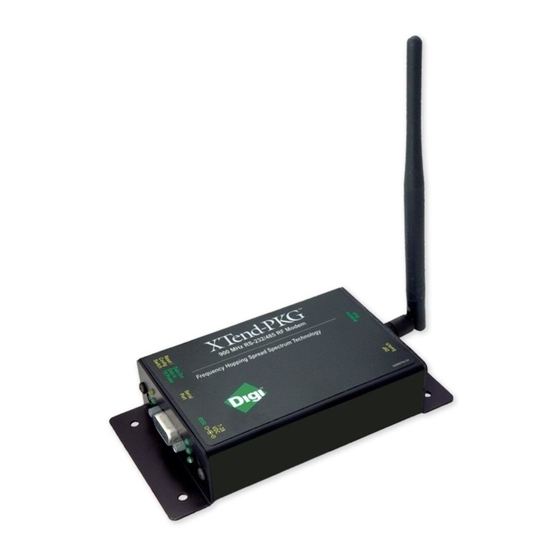
XStream‐PKG‐R™ RS‐232/422/485 RF Modem User’s Guide 1.3. External Interface 1.1a. Power Switch Move the Power Switch to the on (up) position to power the Figure 1.1. Front View Interface Board. DIP Switch [1.2a] settings are only read during a power-up sequence. 1.1b. I/O & Power LEDs The LED indicators visualize diagnostic status information. The modem’s status is represented as follows: Yellow (top LED) = Serial Data Out (to host) Green (middle) = Serial Data In (from host) -
Page 7: Interfacing Protocol
XStream‐PKG‐R™ RS‐232/422/485 RF Modem User’s Guide 2. Interfacing Protocol The XStream-PKG-R RF Modem supports the following interfacing protocols: • RS-232 • RS-485 (2-wire) Half-Duplex • RS-485 (4-wire) and RS-422 2.1. RS-232 Operation 2.1.1. DIP Switch Settings and Pin Signals Figure 2.1. Figure 2.2. ... - Page 8 XStream‐PKG‐R™ RS‐232/422/485 RF Modem User’s Guide Wiring Diagram: RS-232 DTE Device to a DCE RF Modem Figure 2.3. RS‐232 DTE (male connector) device wired to an XStream RF Modem (female connector) Wiring Diagram: DCE RF Modem to an RS-232 DCE Device Figure 2.4. XStream RF Modem (female connector) wired to an RS‐232 DTE (male connector) device Sample Wireless Connection: DTE Figure 2.5. Typical wireless link between DTE and DCE devices 8 ...
-
Page 9: Rs-485 (2-Wire) Operation
XStream‐PKG‐R™ RS‐232/422/485 RF Modem User’s Guide 2.2. RS-485 (2-wire) Operation 2.2.1. DIP Switch Settings and Pin Signals Figure 2.6. Figure 2.7. RS‐485 (2‐wire) Half‐Duplex Pins used on the female RS‐232 (DB‐9) DIP Switch Settings Serial Connector Figure 2.8. ... -
Page 10: Rs-485 (4-Wire) & Rs-422 Operation
XStream‐PKG‐R™ RS‐232/422/485 RF Modem User’s Guide 2.3. RS-485 (4-wire) & RS-422 Operation 2.3.1. DIP Switch Settings and Pin Signals Figure 2.10. Figure 2.11. RS‐485 (4‐wire) and RS‐422 Pins used on the female RS‐232 (DB‐9) DIP Switch Settings Serial Connector Figure 2.12. ... - Page 11 XStream‐PKG‐R™ RS‐232/422/485 RF Modem User’s Guide Wiring Diagram: RS-422 Figure 2.14. XStream RF Modem in an RS‐485 (4‐wire) environment RS-485/422 Connection Guidelines The RS-485/422 protocol provides a solution for wired communications that can tolerate high noise and push signals over long cable lengths. RS-485/422 signals can communicate as far as 4000 feet (1200 m). RS-232 signals are suitable for cable distances up to 100 feet (30.5 m). RS-485 offers multi-drop capability in which up to 32 nodes can be connected.
-
Page 12: Rf Modem Operation
Number of Stop Bits (NB parameter = 0) Both the XStream RF Modem and host (PC) settings can be viewed and adjusted using Digi’s proprietary X-CTU Software. Use the “PC Settings” tab to configure host settings. Use the “Terminal” or “Modem Configuration” tabs to configure the RF Modem settings. Refer to the RF Modem Configuration sections for more information [p21]. -
Page 13: Flow Control
XStream‐PKG‐R™ RS‐232/422/485 RF Modem User’s Guide 3.1.3. Flow Control Figure 3.2. Internal Data Flow Diagram (The five most commonly‐used pin signals are shown.) DI (Data In) Buffer and Flow Control When serial data enters the XStream Modem through the DI Pin, then the data is stored in the DI Buffer until it can be transmitted. When the RO parameter threshold is satisfied (refer to Transmit Mode [p14] and Command Descriptions [p25] sections for more information), the modem attempts to initialize an RF connection. -
Page 14: Modes Of Operation
XStream‐PKG‐R™ RS‐232/422/485 RF Modem User’s Guide 3.2. Modes of Operation XStream RF Modems operate in five modes. Figure 3.3. XStream Modes of Operation Modem can only be in one mode at a time. 3.2.1. Idle Mode When not receiving or transmitting data, the modem is in Idle Mode. The modem uses the same amount of power in Idle Mode as it does in Receive Mode. The modem shifts into the other modes of operation under the following conditions: •... - Page 15 XStream‐PKG‐R™ RS‐232/422/485 RF Modem User’s Guide RF Packet The RF packet is the sequence of data used for communicating information between Digi Modems. An RF Packet consists of an RF Initializer and RF Data. Figure 3.5. RF Packet Components * When streaming multiple RF packets, the RF Initializer is only sent in front of the first packet.
-
Page 16: Receive Mode
XStream‐PKG‐R™ RS‐232/422/485 RF Modem User’s Guide 3.2.3. Receive Mode If a modem detects RF data while operating in Idle Mode, the modem transitions into Receive Mode to start receiving RF packets. Figure 3.7. Reception of RF Data After a packet is received, the modem checks the CRC (cyclic redundancy check) to ensure that the data was transmitted without error. - Page 17 XStream‐PKG‐R™ RS‐232/422/485 RF Modem User’s Guide Pin Sleep (SM = 1) Pin Sleep requires the least amount of power. In order to achieve this state, DI3 (SLEEP) pin must be asserted (high). The modem remains in Pin Sleep until the DI3 pin is de-asserted. After enabling Pin Sleep, the SLEEP pin controls whether the XStream Modem is active or in Sleep Mode.
- Page 18 XStream‐PKG‐R™ RS‐232/422/485 RF Modem User’s Guide Cyclic Scanning. Each RF transmission consists of an RF Initializer and payload. The wake-up initializer contains initialization information and all receiving modems must wake during the wake-up initializer portion of data transmission in order to be synchronized with the transmitting modem and receive the data.
-
Page 19: Command Mode
XStream‐PKG‐R™ RS‐232/422/485 RF Modem User’s Guide 3.2.5. Command Mode To modify or read modem parameters, the modem must first enter into Command Mode, the state in which incoming characters are interpreted as commands. Two command types are available for programming the modem: • AT Commands •... - Page 20 XStream‐PKG‐R™ RS‐232/422/485 RF Modem User’s Guide Binary Commands Sending and receiving parameter values using binary commands is the fastest way to change operating parameters of the XStream RF Modem. Binary commands are used most often to sample signal strength (RS parameter) and/or error counts; or change modem addresses and channels for polling data systems.
-
Page 21: Rf Modem Configuration
XStream‐PKG‐R™ RS‐232/422/485 RF Modem User’s Guide 4. RF Modem Configuration 4.1. Automatic DIP Switch Configurations Each time the RF Modem is powered-on, intelligence on the XIB-R Interface Board (RS-232/485 interfacing board located inside the RF Modem) sends AT Commands that program the RF Modem based on positions of the DIP Switch. Automatic configurations that take place during the power- on sequence affect stored RF Modem parameter values as shown in the tables below. -
Page 22: Programming The Modem
Command Mode section [p19]. 4.2.1. AT Command Examples Digi has provided X-CTU software for programming the modem using an extensive list of AT Commands. The X-CTU software provides an interface that is divided into four tabs that facilitate the following functions: •... -
Page 23: Binary Command Example
The following steps show how to read currently stored modem parameter values; then restore the modem parameters to their factory-default states. Open the X-CTU program (Start --> Programs --> Digi-MaxStream --> X-CTU): Under the “PC Settings” tab, select the PC Serial Com Port from the dropdown list that will be used to connect to the RF Modem. -
Page 24: Command Reference Table
XStream‐PKG‐R™ RS‐232/422/485 RF Modem User’s Guide 4.3. Command Reference Table Table 4.1 XStream Commands (The XStream RF Modem expects numerical values in hexadecimal. “d” denotes decimal equivalent.) Binary # Bytes Factory AT Command Name Range Command Category Command Command Returned Default 0x05 (5d) Guard Time After 0x02 – 0xFFFF [x 100 msec] Command Mode Options 0x0A (10d) Standard baud rates: Set to equal 0 –... -
Page 25: Command Descriptions
BD register. For example, a rate of 19200 bps can be set by sending the following command line "ATBD4B00". NOTE: When using Digi’s X-CTU Software, non-standard interface data rates can only be set and read using the X-CTU ‘Terminal’ tab. Non-standard rates are not accessible through the ‘Modem Configuration’... - Page 26 XStream‐PKG‐R™ RS‐232/422/485 RF Modem User’s Guide BT (Guard Time Before) Command AT Command: ATBT <Command Mode Options> BT Command is Binary Command: 0x04 (4 decimal) used to set the DI pin silence time that must Parameter Range: 2 – 0xFFFF precede the command sequence character (CC [x 100 milliseconds] Command) of the AT Command Mode Sequence.
- Page 27 XStream‐PKG‐R™ RS‐232/422/485 RF Modem User’s Guide CT (Command Mode Timeout) Command <Command Mode Options> CT Command sets AT Command: ATCT the amount of time before AT Command Mode Binary Command: 0x06 (6 decimal) terminates automatically. After a CT time of Parameter Range: 0x02 – 0xFFFF inactivity, the modem exits AT Command Mode [x 100 milliseconds] and returns to Idle Mode.
- Page 28 XStream‐PKG‐R™ RS‐232/422/485 RF Modem User’s Guide FL (Software Flow Control) Command AT Command: ATFL <Serial Interfacing> FL Command is used to configure software flow control. Hardware flow Binary Command: 0x07 (7 decimal) control is implemented with the XStream Modem Parameter Range: 0 – 1 as the DO2 pin ( ), which regulates when Parameter Configuration...
- Page 29 XStream‐PKG‐R™ RS‐232/422/485 RF Modem User’s Guide HT (Time before Wake-up Initializer) Command <<Sleep (Low Power)> If any modems within AT Command: ATHT range are running in a “Cyclic Sleep” setting, a Binary Command: 0x03 (3 decimal) wake-up initializer must be used by the Parameter Range: 0 – 0xFFFF transmitting modem for sleeping modems to [x 100 milliseconds] remain awake [refer to the LH (“Wake-up...
- Page 30 XStream‐PKG‐R™ RS‐232/422/485 RF Modem User’s Guide MK (Address Mask) Command <Networking> MK Command is used to set/read AT Command: ATMK the Address Mask. Binary Command: 0x12 (18 decimal) All data packets contain the Destination Address Parameter Range: 0 – 0xFFFF of the transmitting modem. When an RF data Default Parameter Value: 0xFFFF packet is received, the transmitter’s Destination (Destination address (DT parameter) of the...
- Page 31 XStream‐PKG‐R™ RS‐232/422/485 RF Modem User’s Guide PW (Pin Wake-up) Command AT Command: ATPW <Sleep (Low Power)> Under normal operation, a modem in Cyclic Sleep Mode cycles from an Binary Command: 0x1D (29 decimal) active state to a low-power state at regular Parameter Range: 0 – 1 intervals until data is ready to be received.
- Page 32 XStream‐PKG‐R™ RS‐232/422/485 RF Modem User’s Guide RP (RSSI PWM Timer) Command <Diagnostics> RP Command is used to enable a AT Command: ATRP PWM (“Pulse Width Modulation”) output on the Binary Command: 0x22 (34 decimal) Config pin which is calibrated to show the level Parameter Range: 0 - 0x7F the received RF signal is above the sensitivity [x 100 milliseconds] level of the modem.
- Page 33 XStream‐PKG‐R™ RS‐232/422/485 RF Modem User’s Guide RT (DI2 Configuration) Command AT Command: ATRT <Serial Interfacing> RT command is used to dictate the behavior of the DI2/ /CMD line. RT Binary Command: 0x16 (22 decimal) Command must be issued to enable flow Parameter Range: 0 – 2 control or binary programming.
- Page 34 XStream‐PKG‐R™ RS‐232/422/485 RF Modem User’s Guide SM (Sleep Mode) Command AT Command: ATSM <Sleep Mode (Low Power)> SM Command is used to adjust Sleep Mode settings. By default, Binary Command: 0x01 Sleep Mode is disabled and the modem remains Parameter Range: 0 – 8 continually active. SM Command allows the Parameter Configuration modem to run in a lower-power state and be...
- Page 35 XStream‐PKG‐R™ RS‐232/422/485 RF Modem User’s Guide SY Command allows the modems to remove this information from the RF Initializer after the initial synchronization. For example, changing the SY Parameter to 0x14 (20 decimal) allows all modems to remain in sync for 2 seconds after the last data packet was received. Synchronization information is not re-sent unless transmission stops for more than 2 seconds.
-
Page 36: Appendix A: Agency Certifications
IMPORTANT: The 9XStream (900 MHz) and 24XStream (2.4 GHz) OEM Modems have been certified by the FCC for use with other products without any further certification (as per FCC section 2.1091). Changes or modifications not expressly approved by Digi could void the user’s authority to operate the equipment. -
Page 37: Oem Labeling Requirements
Radio Modems (including “Mag Mount”, “Dome”, “Multi-path” and “Panel” antennas). Because of the large number of approved antennas, Digi requests that you send specific information about an antenna you would like to use with the modem and Digi will evaluate whether the antenna is covered under our FCC filing. -
Page 38: Fcc-Approved Antennas
Type Gain Application Min. Separation Distance Yagi 6.2 dBi Fixed/Mobile ** 20 cm Yagi 7.2 dBi Fixed/Mobile ** 20 cm Digi A09-Y8 Yagi 8.2 dBi Fixed/Mobile ** 20 cm Yagi 9.2 dBi Fixed/Mobile ** 20 cm Yagi 10.2 dBi Fixed/Mobile **... -
Page 39: European Compliance (2.4 Ghz Only)
EMC and safety. Files are located in the ‘documentation’ folder of the Digi CD. Important Note Digi does not list the entire set of standards that must be met for each country. Digi customers assume full responsibility for learning and meeting the required guidelines for each country in their distribution market. -
Page 40: Europe (2.4 Ghz) Approved Antenna List
• Modulation: Frequency Shift Keying • Channel Spacing: 400 kHz • ITU Classification: 400KF1D • Output Power: 100 mW EIRP • Notified Body Number: 0891 Contact Digi if additional information is required. Europe (2.4 GHz) Approved Antenna List Table A.3. Antennas approved for use with 24XStream (2.4 GHz) RF Modems in Europe Minimum Separation... -
Page 41: Appendix B: Development Guide
For example: Part number “X09-019PKC-RA” includes the listed accessories and part number “X09-019PKC-R” does not. The accessories kit includes hardware and software needed for developing long range wireless links. For testing the modem’s range, Digi recommends the purchase of one RF Modem with the accessories and one without. -
Page 42: Adapters
(DTE). Figure B.2. Male NULL modem adapter and pinouts Figure B.3. Example of a Digi Radio Modem (DCE Device) connecting to another DCE device) NULL Modem Adapter (female-to-female) Part Number: JD3D3-CDN-A (Gray, DB-9 F-F) The female-to-female NULL modem adapter is used to verify serial cabling is functioning properly. To test cables, insert the female-to-female NULL modem adapter in place of a pair of modem assemblies (XIB-R-R interface board + XStream Modem) and test the connection without radio modems in the connection. - Page 43 As a general rule, it is best to keep the RF cable as short as possible. All cables promote signal loss which is usually measured in dB loss per 100 ft. Digi provides LMR-195 rated cables. Common cables and dB losses are included in this table: Table B.2.
- Page 44 All replaced Product and parts become the property of Digi. If Digi determines that the Product is not under warranty, it will, at the Customers option, repair the Product using current Digi standard rates for parts and labor, and return the Product UPS Ground at no charge in or out of warranty.
Need help?
Do you have a question about the XStream-PKG-R RS-232 and is the answer not in the manual?
Questions and answers