Table of Contents
Advertisement
Quick Links
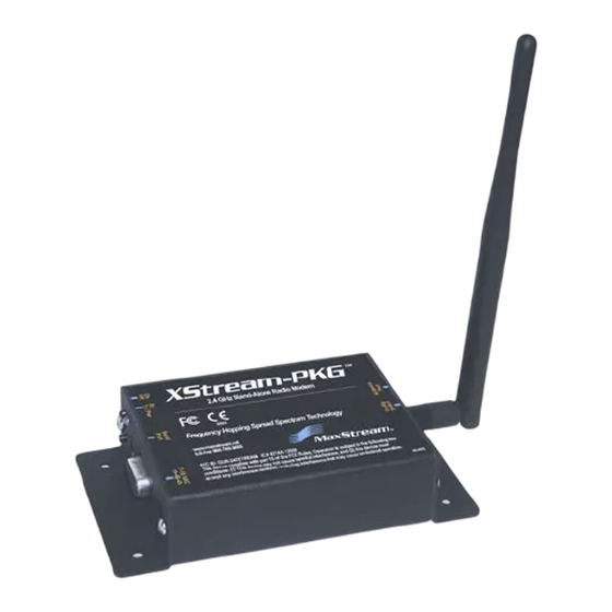
XSt r e a m - PKG- E™ Et h e rn e t RF M ode m
Pr oduct M a n ua l
For XSt ream RF Modem Part Num bers
Re lia ble 9 0 0 M H z a n d 2 .4 GH z St a nd- a lon e RF M ode m s by D igi I n t e r na t ion a l I n c.
v4 .2 B5
X09- 001PK...- E...
X09- 009PK...- E...
X09- 019PK...- E...
X24- 009PK...- E...
XH9-001PK...- E...
X24- 019PK...- E...
XH9- 009PK...- E...
XH9- 019PK...- E...
Advertisement
Chapters
Table of Contents

Subscribe to Our Youtube Channel
Related Manuals for Digi XStream-PKG-E X09-001PK E Series


Summary of Contents for Digi XStream-PKG-E X09-001PK E Series
- Page 1 XSt r e a m - PKG- E™ Et h e rn e t RF M ode m Pr oduct M a n ua l v4 .2 B5 For XSt ream RF Modem Part Num bers X09- 001PK…- E… X24- 009PK…- E... XH9-001PK…- E...
- Page 2 © 2 0 1 4 D igi I nt e r n a t iona l I nc. All r ight s r e se r v e d. ® Digi, Digi International Inc., the Digi logo, and XStream trademarks or registered trademarks in the United States and other countries worldwide.
-
Page 3: Table Of Contents
4.1.3. Binary Com m and Mode 4 .2 . Com m a n d Re fe r e n ce Ta ble 4 .3 . Com m a n d D e scr ipt ion s © 2014 Digi International Inc. -
Page 4: Xstream Ethernet Rf Modem
FCC Ce r t ifie d ( USA) Refer to Appendix A for FCC Requirem ent s. Devices t hat cont ain XSt ream RF Modem s inher it Digi’s FCC Cert ificat ion. I SM ( I ndust r ial, Scient ific and Medical) frequency band... -
Page 5: Pr Oduct Over View
½ wave dipole whip, 6.75” (17.1 cm), 2.1 dBi Gain Connector Reverse-polarity SMA (RPSMA) Impedance 50 ohms unbalanced Certifications FCC Part 15.247 OUR9XSTREAM OUR-24XSTREAM Industry Canada (IC) 4214A-9XSTREAM 4214A 12008 * Divide by 2 for 18V supply (constant wattage from 7 to 28V) © 2014 Digi International Inc. -
Page 6: Ex T E R Na L I Nt E R Fa Ce
Reset Swit ch; t hen aft er 1 sec., release t he Config Switch. The RF Modem t hen ent ers AT Com m and Mode at the m odem ’s default baud rat e. © 2014 Digi International Inc. -
Page 7: System Setup
2 .1 .1 . Syst e m D e scr ipt ion The PKG- E Et hernet RF Modem can be used as an access point in a net work of Digi RS- 232/ RS- 485 RF Modem s (or ot her OEM RF Module Em bedded Devices) . XStream RF Modem s support point - t o- point , peer-to- peer, point - to-m ult ipoint and m ult idrop network t opologies. -
Page 8: Com Por T Com M Unica T Ions
Device I nst aller and Com Port Redirector. 2 .2 .2 . Ra nge Te st ( XCTU) When t est ing a wireless link, Digi suggests creat ing t he link using the following com ponent s: •... -
Page 9: Rf Modem Operation
Sleep Mode condit ion is m et ( Sleep Mode) Aft er responding t o any of t he preceding condit ions, t he m odem aut om at ically t ransit ions back int o I dle Mode. © 2014 Digi International Inc. -
Page 10: Tr A Nsm It M Ode 1
3 .2 .1 . RF Pa ck e t The RF packet is t he sequence of dat a used for com m unicat ing inform at ion bet ween Digi Modem s. An RF Packet consist s of an RF I nit ializer and RF Dat a. -
Page 11: Re Ce Iv E M Ode 1
Receive Mode, t he serial dat a will be transm it ted after t he m odem is finished receiving dat a and ret urns t o I dle Mode. © 2014 Digi International Inc. -
Page 12: Sle Ep M Ode 1
( no t ransm it t ing or receiving of dat a) . This period of t im e is det erm ined by ST ( Tim e before Sleep) Com m and. Once a charact er is received t hrough t he DI pin, t he m odem ret urns to I dle Mode and is fully operat ional. © 2014 Digi International Inc. - Page 13 Figure 3‐07. Incorrect Configuration (LH < SM) Length of wake‐up initializer is shorter than the time interval of Cyclic Sleep. This configuration is vulnerable to the receiver waking and missing the wake‐up initializer (and therefore also the accompanying payload data). © 2014 Digi International Inc.
-
Page 14: Com M A N D M Ode 1
For exam ples t hat st ep t hrough t he program m ing t he m odem using AT Com m ands, refer to t he RF Modem Configurat ion ( p20) chapter . © 2014 Digi International Inc. -
Page 15: Binary Com M And Mode
Configuration) parameter must be set to one. If binary programming is not enabled (RT ≠ 1), the modem will not recognize that the CMD pin is asserted and therefore will not recognize the data as binary commands. © 2014 Digi International Inc. -
Page 16: Rf M Ode M Configur A T Ion 1
For m ore inform at ion about ent ering Com m and Mode, sending Examples in this section com m ands and exit ing Com m and Mode, refer t o t he Com m and Mode cite the use of Digi’s XCTU sect ion ( p18) . Software for programming the RF modem. -
Page 17: At Com M And Mode
( Most significant byt e of param et er byt es) ( Send WR ( Wr it e) Com m and) De- assert CMD ( Pin is driven low) . ( Exit Binary Com m and Mode) © 2014 Digi International Inc. -
Page 18: Com M A N D Re Fe R E N Ce Ta Ble 1
0 x 0xFFFF (Read-only) Diagnostic 0x08 (8d) Write (Special) * Firmware version in which the command and parameter options were first supported. NOTE: Commands issued without a parameter value will return the currently stored parameter. © 2014 Digi International Inc. -
Page 19: Com M A Nd D E Scr Ipt Ions
BD register. For exam ple, a rat e of 19200 bps can be set by sending t he following com m and line "ATBD4B00" . NOTE: When using Digi’s XCTU Soft ware, non- st andard int erface dat a rat es can only be set and read using t he XCTU “... - Page 20 By default , DO2 provides RS- 232 ( Clear- t o- RS-485 TX enable high Send) flow cont rol. Default Parameter Value: 0 Number of bytes returned: 1 Related Commands: RT (DI2 Configuration), TO (DO2 Timeout) Minimum Firmware Version Required: 4.27D © 2014 Digi International Inc.
- Page 21 . WR ( Writ e) Com m and does not need to be issued wit h FH Com m and. Use only wit h cyclic sleep m odes act ive on rem ot e m odem s. © 2014 Digi International Inc.
- Page 22 ID (Modem VID), MK (Address Mask) Differ ent channels can be used t o prevent m odem s in one network from list ening to t ransm issions of anot her. © 2014 Digi International Inc.
-
Page 23: Default Parameter Value: 1
< Net working> Read t he m odem ’s VI D. VI D is a AT Command: ATID Digi-specific acronym that st ands for “ Vendor Binary Command: 0x27 (39 decimal) I dent ificat ion Num ber” . This num ber is fact ory-... -
Page 24: Default Parameter Value: 0
( low) , the m odem will Wake-up AT Command Mode int o AT Com m and Mode. This behavior allows Default Parameter Value: 0 Number of bytes returned: 1 m odem DTR em ulat ion. Minimum Firmware Version Required: 4.22 © 2014 Digi International Inc. - Page 25 Default Parameter Value: 0 received before t he RO t im eout , t he transm ission Number of bytes returned: 2 will st art . Minimum Firmware Version Required: 4.2AA © 2014 Digi International Inc.
-
Page 26: Number Of Bytes Returned: 1
Once t he com m and is issued, the m odem will return a value bet ween 0x6 and 0x36 where 0x36 represent s a very strong signal level and 0x4 indicat es a low signal level. © 2014 Digi International Inc. - Page 27 AT Command: ATSH word of t he m odem . Binary Command: 0x26 (38 decimal) Parameter Range: 0 – 0xFFFF (Read-only) Number of bytes returned: 2 Related Commands: SH (Serial Number High) Minimum Firmware Version Required: 4.27C © 2014 Digi International Inc.
-
Page 28: Parameter Range
I f no new m odem s are intr oduced int o t he syst em , t he synchronizat ion inform at ion becom es redundant once m odem s have becom e synchronized. © 2014 Digi International Inc. -
Page 29: Default Parameter Value: 0
I f changes are m ade wit hout writ ing t hem t o non-volat ile m em ory, t he m odem revert s back to previously saved par am et ers the next t im e t he m odem is powered- on. © 2014 Digi International Inc. -
Page 30: Appe Ndix A: Age Ncy Ce Rt Ifica T Ions 3
IMPORTANT: The 9XStream (900 MHz) and 24XStream (2.4 GHz) RF Modems have been certified by the FCC for use with other products without any further certification (as per FCC section 2.1091). Changes or modifications not expressly approved by Digi could void the user’s authority to operate the equipment. -
Page 31: Oem Labeling Requirem Ent S
Digi request s t hat you send specific inform at ion about an ant enna you would like to use wit h t he m odem and Digi will evaluat e whet her t he ant enna is covered under our FCC filing. -
Page 32: Fcc Approved Ant Ennas
20 cm Monopole 1.9 dBi Fixed/Mobile ** 20cm * FCC‐approved antennas not inventoried by Digi – Contact Digi (866) 765‐9885 for information. ** Can be approved for portable applications if integrator gains approval through SAR testing © 2014 Digi International Inc. -
Page 33: I C ( I Ndust R Y Ca Na Da ) Ce R T Ifica T Ion
- Unint ent ional Radiators. I CES- 003 is t he sam e as FCC Part 15 Sub. B and I ndust ry Canada accept s FCC test r epor t or CI SPR 22 t est report for com pliance wit h I CES- 003. © 2014 Digi International Inc. -
Page 34: Appe Ndix B: Addit Iona L I Nfor M A T Ion 3
Digi, shipping prepaid, for prompt repair or replacement. The foregoing sets forth the full extent of Digi's warranties regarding the Product. Repair or replacement at Digi's option is the exclusive remedy. THIS WARRANTY IS GIVEN IN LIEU OF ALL OTHER WARRANTIES, EXPRESS OR IMPLIED, AND DIGI SPECIFICALLY DISCLAIMS ALL WARRANTIES OF MERCHANTABILITY OR FITNESS FOR A PARTICULAR PURPOSE. -
Page 35: Con T A Ct D Igi 3
Phone ( 866) 765- 9885 toll- free U.S. and Canada ( 801) 765- 9885 Worldwide 8 : 00 am – 5: 00 pm ( U.S. Cent ral Tim e) Online www.digi.com / support / eservice © 2014 Digi International Inc.
Need help?
Do you have a question about the XStream-PKG-E X09-001PK E Series and is the answer not in the manual?
Questions and answers