Table of Contents
Advertisement
Advertisement
Table of Contents

Related Manuals for CNET CBR-980


Summary of Contents for CNET CBR-980
-
Page 1: User Manual
CBR-980 Wireless-N Broadband Router User Manual Version 1.0 (Dec, 2009) -
Page 2: Table Of Contents
Product Appearance .................... 8 1.4.2 Hardware Specifications ..................8 CHAPTER 2 SYSTEM AND NETWORK SETUP ..............9 Build Network Connection ..................9 Connecting to CBR-980 by Web Browser .............. 10 2.2.1 Windows 95/98/ME ....................11 2.2.2 Windows 2000 ...................... 13 2.2.3 Windows XP ...................... - Page 3 5.1.1.2 WAN Interface – Ethernet Port ................42 5.1.1.3 WAN Interface – WiMAX ..................43 5.1.1.4 WAN Access Type – Wireless ................43 5.1.1.5 WAN Access Type – Static IP ................. 45 5.1.1.6 WAN Access -- Dynamic IP ..................47 5.1.1.7 WAN Access Type -- PPPoE ..................
- Page 4 Support ........................ 115 Others ........................116 USB Device ......................116...
-
Page 5: Preface
This manual includes description of the management interface and detailed instruction in its use. Conventions Used • Notes, warnings or cautions are in bold with shaded background. • In this manual, the CBR-980 Wireless-N Broadband Router is referred to as “the wireless router”. -
Page 6: Chapter 1 Introduction
Introduction About CBR-980 CBR-980 is not only a Wireless-N Router, It also equips with two USB 2.0 hosts to provides users with high-speed WiMAX / 3.5G mobile network, connectivity. CBR-980 provides Multi-SSIDs for difference network environment and application. For the heavy P2P user that the high efficiency CPU speeds up P2P download with 20,000 sessions. -
Page 7: Getting To Know Cbr-980
Getting to Know CBR-980 The front view of CBR-980 Status Solid Flashing LED Indicator Operation OK Power on POWER Green: Reset/Firmware updates in STATUS Operation OK progress Green: Transmitting Data WIRELESS & WPS Operation OK Orange: Establishing WPS Internet OK... -
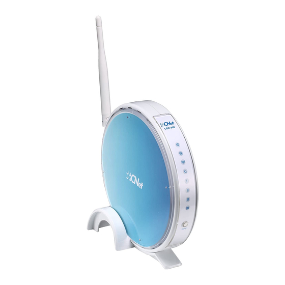
Page 8: Product Appearance
1.4.1 Product Appearance Power Receptor Adapter, Input:90-240Vac, Output: 5V/ 1.2A Press “Reset” button over 10 seconds. When status indicator turns from Reset Button flashing to solid, the process is completed. All settings are back to default. Ethernet Port 1x WAN port, 4x LAN ports USB2.0 Ports 1 USB Ports 1.4.2... -
Page 9: System And Network Setup
Chapter 2 System and Network Setup The CBR-980 is an easy to setup and wireless device for various application and environment. It can be used in conference room, hotel, even in transportation. The USB port could connect with USB WiMAX / 3.5G dongle. -
Page 10: Connecting To Cbr-980 By Web Browser
Connecting to CBR-980 by Web Browser After the network connection is built, the next step what you should do is setup the router with proper network parameters, so it can work properly in your network environment. Before you connect to the wireless router and start configuration procedures, your computer must be able to get an IP address from the wireless router automatically (use dynamic IP address). -
Page 11: Windows 95/98/Me
2.2.1 Windows 95/98/ME 1. Click ‘Start’ button (it should be located at lower-left corner of your computer), then click control panel. Double-click Network icon, and Network window will appear. Select ‘TCP/IP’, then click ‘Properties’. 2. Select ‘Obtain an IP address from a DHCP server’, and then click ‘OK’. -
Page 13: Windows 2000
2.2.2 Windows 2000 Click ‘Start’ button (it should be located at lower-left corner of your computer), then click control panel. Double-click Network and Dial-up Connections icon, double click Local Area Connection, and Local Area Connection Properties window will appear. Select ‘Internet Protocol (TCP/IP)’, then click ‘Properties’. -
Page 15: Windows Xp
2.2.3 Windows XP 1. Click ‘Start’ button (it should be located at lower-left corner of your computer), then click control panel. Double-click Network and Internet Connections icon, click Network Connections, then double-click Local Area Connection, Local Area Connection Status window will appear, and then click ‘Properties’. -
Page 17: Windows Vista
2.2.4 Windows Vista 1. Click ‘Start’ button (it should be located at lower-left corner of your computer), then click control panel. Click View Network Status and Tasks, and then click Manage Network Connections. Right-click Local Area Netwrok, then select ‘Properties’. Local Area Connection Properties window will appear, select ‘Internet Protocol Version 4 (TCP / IPv4), and then click ‘Properties’. -
Page 19: Router Ip Address Lookup
2.2.5 Router IP Address Lookup After the IP address setup was completed, please clicks ‘start’ ‘run’ at the bottom-lower corner of your desktop: Input ‘cmd’, and then click ‘OK’ Input ‘ipconfig’, then press ‘Enter’ key. Please check the IP address followed by ‘Default Gateway’ (In this example, the gateway IP address of router is 192.168.1.1) -
Page 20: Connect The Wireless Router's Management Interface By Web Browser
After your computer obtained an IP address from wireless router, please start your web browser, and input the IP address of the wireless router in address bar, and the following message should be shown. Please click “Administrator” to login the CBR-980. Notes: The default IP of the wireless router is 192.168.1.1 Please input user name and password in the field respectively. - Page 21 NOTE: If you can’t see the web management interface, and you’re being prompted to input user name and password again, it means you didn’t input username and password correctly. Please retype user name and password again. If you’re certain about the user name and password what you type are correct, please go to ‘Troubleshooting’...
-
Page 22: Chapter 3 One Button Setup Configuration
One Button Setup Configuration CBR-980 “One Button Setup” will help you to setup the basic setting of the wireless router with simplify procedure. You do not need to learn much complicated network proper name but you still can setup the wireless router by yourself. - Page 23 Item Description Press button to choose a time zone of the location you live from Time Zone Select the drop-down list. Change Password Input new password here Device Name Input new device name here Choose the broadband interface you are using. The wireless router WAN Interface Setup supports Ethernet Port / 3.5G USB dongle / WiMAX / Wireless 4 different types interfaces...
-
Page 24: Chapter 4 Quick Setup Configuration
Quick Setup Configuration There are two way to connect to CBR-980 setup page. A. Use Internet browser to connect to CBR-980 1. Please open your Internet browser, for example like IE or Firefox, and input the CBR-980 IP address, http://192.168.1.1 Login page will shown as below, and enter username / password. - Page 25 Click “Internet Gateway Device” to enter the login page...
-
Page 26: Step Setup
NOTE: Please click the “Finish” button to save the entire configuration and complete the step setting Click on Step Setup in the left screen of the main menu, and click “Step Setup”, then click “Next” to start configure your CBR-980. 4.1.1 Time Zone Setup... -
Page 27: Lan Interface Setup
4.1.2 LAN Interface Setup Item Description Device Name Fill in the name for the wireless router IP Address The wireless router IP address After you finish all of the setting, please click “Next” button to enter next step. 4.1.3 WAN Interface Setup The WAN settings can be referred to as the Public setting. -
Page 28: Wan Interface - Ethernet Port
4.1.3.2 WAN Interface – Ethernet Port If you are using an Ethernet cable to connect the Internet, please select Ethernet port. -
Page 30: Wan Access Type - Wimax
4.1.3.3 WAN Access Type – WiMAX If you are using WiMAX as the WAN Type, please select WiMAX and fill in the required information as follows to directly access Internet via connected WiMAX adapter. 4.1.3.4 WAN Access Type – Wireless If you are connecting the internet via wireless, please select Wireless and its associated settings will show up underneath at the same time. -
Page 31: Wan Access Type - Static Ip
You can see a list of available Wireless networks. Select you preferred one to connect and the Encryption type form the drop-down list. 4.1.3.5 WAN Access Type – Static IP Choose Static IP Address if all WAN IP information is provided to you by your ISP. You will need to enter the IP address, IP Netmask and IP gateway as provided. - Page 32 automatically connects Internet via 3.5G adapter. If 3.5G signal is not available, it starts to search downward for 3/2.75/2.5G signals until none existed. The default interval between the two connection detection is 3 minutes. The interval range is from 1 to 60 minutes. The 3.5G feature is working as mutual backup for other 3 WAN Types, and the required information is listed as follows, such as user name, password and SIM PIN etc.
-
Page 33: Wan Access Type - Dynamic Ip
4.1.3.6 WAN Access Type – Dynamic IP Choose Dynamic IP to obtain IP address information automatically from your ISP. Select this option if your ISP does not give you any IP numbers to use. This option is commonly used for Cable modem services. -
Page 34: Wan Access Type - Pppoe
4.1.3.7 WAN Access Type – PPPoE This option is typically used for DSL services. Choose PPPoE (Point to Point Protocol over Ethernet) if your ISP uses PPPoE connection. Your ISP will provide you with a username and password. Apply 3G or 3.5G transmission rate for the backup. In other words, once PPPoE connection is disconnected, the system automatically connects Internet via 3.5G adapter. -
Page 35: Wan Access Type -- Pptp
4.1.3.8 WAN Access Type -- PPTP This option is typically used for DSL services. Some DSL service providers supply a special DSL modem. This kind of modem only supports the PPTP tunnel to access the Internet, you should create a PPTP tunnel that carries a PPP session and terminates on the DSL model. -
Page 36: Wireless Setup
Click on Next button to go on next setting page. 4.1.4 Wireless Setup First step is to name your SSID, and the default value is Download Server Router. Please follow the illustrations below to proceed. -
Page 37: Wireless Security Setup
4.1.4.1 Wireless Security Setup The security function is provided to prevent the connection requests from unauthorized wireless clients. As the Encryption Type, select WEP or WPA can protect your data from eavesdroppers, if you do not need the encryption, select “None” to skip the following setting. a. - Page 38 Item Description There are two types of WEP key length: 64-bit and 128-bit. Using Key Length ‘128-bit’ is more safety than ’64-bit’, but data transfer performance is more lower than ‘64-bit’. There are two types of key format: ASCII and Hex. When you select a key format, the number of characters of key will be displayed.
-
Page 39: Basic Step Complete
Basic Step Complete The Basic Setup has been completed successfully when you see this screen. The system will be rebooted automatically and go to the product’s diagram homepage. You may connect to Internet via wired or wireless at this moment according to above settings. -
Page 40: Chapter 5 Advanced Configuration
Chapter 5 Advanced Configuration This chapter describes how to setup the access the router through the web browser. Please be noted that in order to access the router’s admin page, a computer must be connected to one of the LAN ports on the router. -
Page 41: Wan Interface - 3.5G (Hsdpa/Umts)
5.1.1.1 WAN Interface – 3.5G (HSDPA/UMTS) If you are using HSDPA/UMTS (3.5G connection) as the WAN Type, please select 3.5G USB Dongle. At this moment, Backup of Connection is not available. When 3.5G signal cannot be reached, the system starts to search downward for 3/2.75/2.5G signals until none existed. -
Page 42: Wan Interface - Ethernet Port
5.1.1.2 WAN Interface – Ethernet Port If you are using an Ethernet cable to connect the Internet, please select Ethernet port. -
Page 43: Wan Interface - Wimax
5.1.1.3 WAN Interface – WiMAX If you are using WiMAX as the WAN Type, please select WiMAX and fill in the required information as follows to directly access Internet via connected WiMAX adapter. 5.1.1.4 WAN Access Type – Wireless If you are connecting the internet via wireless, please select Wireless and its associated settings will show up underneath at the same time. - Page 44 You can see a list of available Wireless networks. Select you preferred one to connect and the Encryption type form the drop-down list.
-
Page 45: Wan Access Type - Static Ip
5.1.1.5 WAN Access Type – Static IP If you applied for a Static IP connection type from ISP, please follow the steps to set up your WAN connection. - Page 46 Item Description Please enter the IP address which is provided by your ISP. IP Address If you don’t have it, please contact your ISP. Subnet Mask Please enter the Subnet Mask address. Input ISP Default Gateway Address. If you don’t know, Gateway Default please check with your ISP.
-
Page 47: Wan Access -- Dynamic Ip
5.1.1.6 WAN Access -- Dynamic IP If your WAN access type is Dynamic IP, please complete the settings as following instructions. - Page 48 Item Description The host name is optional; but if your ISP requires you to input a specific host name, please put it in, for example, 11n Host Name Broadband Router applied from ISP. Generally, Cable Modem will provide the hostname information. MTU stands for Maximum Transmission Unit.
-
Page 49: Wan Access Type -- Pppoe
5.1.1.7 WAN Access Type -- PPPoE If you applied for a PPPoE connection type from ISP, please follow the steps to set up your WAN connection. - Page 51 Item Description Input your user name supplied by ISP. If you User Name don’t know, please check with your ISP. Input your Password supplied by ISP Password Input the service name supplied by ISP. Service Name It has three types: Continuous, Connect on Connection Type Demand, and Manual.
-
Page 52: Wan Access Type -- Pptp
Copy the MAC address from the device you had registered to your ISP if your ISP asks for the Clone MAC Address specific MAC Address. The Internet Group Management Protocol (IGMP) is a communications protocol used to manage the membership of Internet Protocol multicast groups. - Page 54 Item Description Input your IP Address supplied by ISP. If you don’t IP Address know, please check with your ISP. Input Subnet Mask, normally it is 255.255.255.0. Subnet Mask Input your Server IP Address supplied by ISP. If you Server IP Address don’t know, please check with your ISP.
-
Page 55: Lan Interface Setup
existed. Copy the MAC address from the device you had registered to your ISP if your ISP asks for the specific Clone MAC Address MAC Address. The Internet Group Management Protocol (IGMP) is a communications protocol used to manage the membership of Internet Protocol multicast groups. - Page 56 Item Description IP Address The default IP address is 192.168.1.1 Subnet Mask Please enter the Subnet Mask address Default Gateway Please enter the Default Gateway address for LAN interface. Click to select Disabled, Client or Server in different operation mode DHCP of LAN access point.
-
Page 57: Dynamic Dns Setting
5.1.3 Dynamic DNS Setting You can assign a fixed host and domain name to a dynamic Internet IP address. Each time the router boots up, it will re-register its domain-name-to-IP-address mapping with the DDNS service provider. This is the way Internet users can access the router through a domain name instead of its IP address. Note: make sure that you have registered with a DDNS service provider before enabling this feature. -
Page 58: Wireless Setup
ODS, Regfish embedded in CBR-980. User name is used as an identity to login Dynamic-DNS User Name/Email service. Password is applied to login Dynamic-DNS service. Password/Key Click on Apply button to continue. Click on Cancel button to Apply & Cancel clear the setting on this page. -
Page 59: Wireless Basic Settings
5.2.1 Wireless Basic Settings The Wireless Basic Settings include Band, Mode, SSID, Channel Number and other wireless settings. - Page 60 Multiple APs provides users another 4 different SSID for connection. Users can add or limit the properties for each connection. Please check Section 5.2.1.1 Service Set identifier, the default SSID is CNet, users can define to SSID any. Channel Width Please select the channel width, it has 2 options: 20MHZ, and 40MHZ.
-
Page 61: Multiple Aps
5.2.1.1 Multiple APs Multiple APs provides users another 4 different SSIDs for connection. Each SSID could be set with different data rate, WMM and access type. Item Description Enable Enable or disable the service. Band Select the frequency. SSID Enter the SSID. Data Rate Select the data transmission rate. -
Page 62: Wireless Advanced Settings
Example: When users enable the Universal Repeater to connect to the upper level device, please fill in the upper level device’s channel and SSID. Click on Apply Changes to save the settings. (Please disable the DHCP service first) Users can go to the network Config section to check the information which about “Wireless Repeater Interface Configuration”. - Page 63 Item Description To identify the maxima length of packet, the over length packet will be Fragment Threshold fragmentized. The allowed range is 256-2346, and default length is 2346 This value should remain at its default setting of 2347. The range is 0~2347. Should you encounter inconsistent data flow, only minor modifications are recommended.
-
Page 64: Wireless Security Setup
extension to IEEE 802.11 that provides wireless access-point communications among multivendor systems. Protection Please select to enable wireless protection or not. Enable this function will combine several packets to one and transmit it. It Aggregation can reduce the problem when mass packets are transmitting. Users can get better wireless transmission efficiency when they enable this Short GI function. - Page 65 802.1x Authentication: It is a safety system by using authentication to protect your wireless network. Encryption – WPA (WPA, WPA2, and WPA2 Mixed), WPA Authentication Mode - Enterprise (RADIUS): Please fill in the RADIUS server Port, IP Address, and Password - Personal (Pre-Shared Key): Pre-Shared Key type is ASCII Code;...
-
Page 66: Wireless Access Control
3. Apply Change & Reset: Click on ‘Apply Changes’ to save setting data. Or click ‘Reset’ to reset all the input data. 5.2.4 Wireless Access Control Access Control allows user to block or allow wireless clients to access this router. Users can select the access control mode, then add a new MAC address with a simple comment and click on “Apply Changes”... - Page 67 (1) Here is the example. Please select Deny Listed in Wireless Access Control Mode first, and then fill in the MAC address what you plan to block in the MAC Address field. Click Apply Changes to save the setting. (2) The MAC address what you set will be displayed on the Current Access Control List. (3) The wireless client will be denied by the wireless router.
-
Page 68: Wds Settings
5.2.5 WDS Settings When selected in the Basic Settings page and enabled here, Wireless Distribution System (WDS) enables the router to be used as a wireless bridge. Two Wireless-G Routers in bridge mode can communicate with each other through their wireless interfaces. To accomplish this, all wireless routers should be set to the same channel and the MAC address of other AP / Routers should be entered in the table. - Page 69 The WDS explanation as the following picture. *Please follow the below instructions to setup the WDS connection. (1) Please check the MAC address and Channel number from the upper lever device.
- Page 70 (2) Set the connection mode to “AP+WDS” from “Wireless Basic Setting”, and then select the channel number(in this example is “11”). Click Apply Changes to save the setting.
- Page 71 (3) Enable WDS function from the page – “WDS Setting”, and then fill in the upper level device MAC address. Click Apply Changes to save the setting data.
- Page 72 (4) The WDS AP List will show the WDS device MAC address after reboot.
- Page 73 (5) Set “Broadcast SSID” to disable from page “Wireless Basic Setting”. (6) Go to the upper level device WDS setting page and fill in the MAC address...
- Page 74 Please input the MAC address of this router. (7) You will receive an IP address from the upper lever device.
-
Page 75: Wps
5.2.6 This page allows user to change the setting for WPS (Wi-Fi Protected Setup). Using this feature could let your wireless client atomically synchronize it’s setting and connect to the Access Point in a minute without any hassle. CWR-854 could support both Self-PIN or PBC modes, or use the WPS button (at real panel) to easy enable the WPS function. - Page 76 When users select a specific model on wireless base station, the clients can connect to the base by selecting the same model. The connection procedures of PIN and PBC are almost the same. The small difference between those two is: Users input the PIN of wireless card in the base station first;...
- Page 77 (2) Click OK to start WPS process. (3) Open the configuration page of the wireless card. Click the Wi-Fi Protect Setup, and then click PBC to start the WPS process. (4) The WPS is being processed.
- Page 78 (5) The USB dongle will receive the connection information from wireless router if the dongle has connected to the wireless router successfully.
- Page 79 * Start PIN: (1.) Get the WPS PIN number from wireless card and write it down. (2) Fill in the PIN number which from the wireless card in CBR-980, and then click “Start PIN”.
- Page 80 (3) Click OK to starts process. (4) Click PIN to start the WPS process with the wireless router.
- Page 81 (5) Click No, then USB Dongle will select AP automatically. (6) WPS is in processing.
- Page 82 (7) The following page shows the wireless card has already connected to the wireless router.
-
Page 83: Nat
5.3.1 Visual Server The Virtual Server feature allows users to create Virtual Servers by re-directing a particular range of service port numbers (from the WAN port) to a particular LAN IP address. Item Description Enable Port Forwarding Select to enable Port Forwarding service or not. IP Address Specify the IP address which receives the incoming packets. -
Page 84: Dmz
*Please find the following figure to know that what the virtual server is. The web server is located on 192.168.1.100, forwarding port is 80, and type is TCP+UDP. Configuration: Private IP: 192.168.1.100 Port: 80 - 80 Type: TCP+UDP 5.3.2 The DMZ feature allows one local user to be exposed to the Internet for special-purpose applications like Internet gaming or videoconferencing. -
Page 85: Firewall
Item Description Enable DMZ It will enable the DMZ service if you select it. DMZ Host IP Address Please enter the specific IP address for DMZ host. Click on Apply Changes to save the setting data. Or you may click on Apply Change &... - Page 86 technologies. The primary goal of QoS is to provide priority including dedicated bandwidth, controlled jitter and latency (required by some real-time and interactive traffic), and improved loss characteristics. Also important is making sure that providing priority for one or more flows does not make other flows fail. QoS technologies provide the elemental building blocks that will be used for future business applications in campus, WAN and service provider networks.
-
Page 87: Port Filtering
Automatic Downlink Speed Click the checkbox to manage downlink speed automatically. Manual Downlink Speed Input the number of downlink speed. Address TypeA Select IP or MAC to manage QoS. Mode Select the type of bandwidth mode. Uplink Bandwidth Please enter the port number of uplink bandwidth. Downlink Bandwidth Please enter the port number of downlink bandwidth. -
Page 88: Ip Filtering
Item Description Enable Port Filtering Please select Enable Port Filtering to filter ports. Port Range Please enter the port number that needs to be filtered. Protocol Please select the protocol type of the port. Comment You can add comments for this regulation. Click on Apply Changes to save the setting data. -
Page 89: Mac Filtering
Item Description Enable IP Filtering Please select Enable IP Filtering to filter IP addresses. Local IP Address Please enter the IP address that needs to be filtered. Protocol Please select the protocol type of the IP address. Comment You can add comments for this regulation. Click on Apply Changes to save the setting data. -
Page 90: Url Filtering
Item Description Enable MAC Filtering Please select Enable MAC Filtering to filter MAC addresses MAC Address Please enter the MAC address that needs to be filtered. Comment You can add comments for this regulation. Click on Apply Changes to save the setting data. Or you may click on Apply Change &... -
Page 91: System Management
Item Description Enable URL Filtering Please select Enable MAC Filtering to filter MAC addresses URL Address Please enter the MAC address that needs to be filtered. Click on Apply Changes to save the setting data. Or you may click on Apply Change &... -
Page 92: Change Password
Click on Apply Changes to save the setting data. Or you may click on Reset to clear all the input data. 5.5.2 Firmware Upgrade The firmware on this wireless router can be easily upgraded. You can check the website (http://www.cnet.com.tw) to see if there is any later version of firmware... -
Page 93: Profile Save
Notes: Do not power off the device while the firmware is being upgraded Caution: To prevent that firmware upgrading is interrupted by other wireless signals and causes failure. We recommend users to use wired connection during upgrading. Caution: The firmware upgrade will not remove your previous settings. *Reset button: On the back of this router, there is a reset button. - Page 94 Save to computer Upload the file from PC to router Reset to default. a. Save Configuration (1) Click Save (2) Please click “Save” to save the configuration to your computer.
- Page 95 (3) Select the location which you want to save file, then click Save. b. Load configuration file (1) Click Browser (2) Select configuration file then click Open...
- Page 96 (3) Click Upload to upload configuration file to CBR-980. (4) After 90 seconds, CBR-980 will reboot automatically. (C) Reload factory default setting 1. Please click Reset...
-
Page 97: Time Zone Setting
(2) Please click OK to start reload factory default setting to CBR-980. (3) After 90 seconds, CBR-980 will reboot automatically. 5.5.4 Time Zone Setting Users can synchronize the local clock on the router to an available NTP server (optional). To complete... -
Page 98: Upnp Setting
Forum. The goals of UPnP are to allow devices to connect seamlessly and to simplify the implementation of networks in the home (data sharing, communications, and entertainment) and in corporate environments for simplified installation of computer components. CBR-980 supports UPnP function, and can cooperate with other UPnP devices. When you activate UPnP, please click My Network Places. -
Page 99: Language Setting
5.5.6 Language Setting CBR-980 provides users with 12 languages to choose. Users can change the language of the interface configuration. Please click Apply Changes after selecting a language. Using Korean as an example, the screen will display on the chosen language as below. -
Page 100: Log & Status
Log & Status The category provides Network Config and Event Log status for users to know the operation status. 5.6.1 Network Config Users can check the Internet status under this category, including Firmware version, Wireless setting, Connecting Time, WAN, TCP/IP …information from this page. -
Page 101: Event Log
5.6.2 Event Log You could enable the event log feature here. Please select to enable log function. Item Description Enable Log You may choose to enable Event Log or not System all, Wireless, DoS Please select the event you want to record. Enable Remote Log You may choose to enable the remote event log or not. -
Page 102: Logout
Apply & Cancel Click on Apply button to add the settings into the list table. Click on Cancel button to clean the setting on this page. *The following figure is an example when users click Apply Changes to record the event log. Logout This function provides users to logout. -
Page 103: Chapter 6 Ddns Account Setup
Chapter 6 DDNS Account Setup You can assign a fixed host and domain name to a dynamic Internet IP address. Each time the router boots up, it will re-register its domain-name-to-IP-address mapping with the DDNS service provider. This is the way Internet users can access the router through a domain name instead of its IP address. 【Step 1】... - Page 104 【Step 3】 When the below window appears, you already finish the registration. Please check your E-mail box, and you will receive an e-mail from the DynDNS.
- Page 105 【Step 4】 Please open the email sent from DynDNS. Click on the link to confirm your account.
- Page 106 【Step 5】 Please click on login. 【Step 6】 Please click on My Services under the Account Summary for the linkage. 【Step 7】 Please click on Add Host Services.
- Page 107 【Step 8】 Please click on Add Dynamic DNS Host. 【Step 9】 1. Please input the account you applied. 2. Please select the hostname preferred at the drop-down menu. 3. Please click on Add Host to add the name.
- Page 108 【Step 10】 When the below window appears, it means your hostname is created.
-
Page 109: Chapter 7 Q & A
Chapter 7 Q & A Installation Q: Where is the XDSL Router installed on the network? A: In a typical environment, the Router is installed between the XDSL line and the LAN. Plug the XDSL Router into the XDSL line on the wall and Ethernet port on the Hub (switch or computer). -
Page 110: Ip Address
IP Address Q: What is the default IP address of the router for LAN port? A: The default IP address is 192.168.1.1 with subnet mask 255.255.255.0 Q: I don't know my WAN IP. A: There are two ways to know. Way 1: Check with your Internet Service Provider. -
Page 111: Broadband Router Setup
displayed on the screen. What do I need to do? A: Force your NIC to 10Mbps or half duplex mode, and turn off the "Auto-negotiate" feature of your NIC as a temporary measure. (Please look at the Network Control Panel, in your Ethernet Adapter's Advanced Properties tab.) Q: Why can't I connect to the Web Configuration? A: you can remove the proxy server settings in your web browser. - Page 112 A: Periodically, a new Flash Code is available for 11n Broadband Router on your product supplier’s website. Ideally, you should update 11n Broadband Router’s Flash Code using Upgrade Firmware on the System Management menu of 11n Broadband Router Settings. Q: My 11N Broadband Router cannot connect to the ISP? A: There are three possible solutions.
-
Page 113: Wireless Lan
Wireless LAN Q: Why couldn’t my wireless notebook work on-line after checking? A: Generally, Wireless networks can sometimes be very complicated to set up, particularly if you're dealing with encryption and products from different vendors. Any number of variables can keep your workstations from talking to each other. Let's go over some of more common ones. - Page 114 Q: My PC can’t locate the Wireless Access Point. A: Check the following: Your PC is set to Infrastructure Mode. (Access Points are always in Infrastructure Mode.) The SSID on your PC and the Wireless Access Point are the same. Remember that the SSID is case-sensitive.
- Page 115 A: The Wireless Router processes the data passing through it, so it is not transparent. Use the Special Application feature to allow the use of Internet applications which do not function correctly. If this does solve the problem, you can use the DMZ function. This should work with almost every application, but: ...
- Page 116 Others Q: Why can’t I receive corrupted FTP downloads? A: If you are experiencing corrupted files when you download a file with your FTP client, try using another FTP program. Q: Why does the router dial out for PPPoE mode very often? A: Normally some of game, music or anti-virus program will send out packets that trigger the router to dial out, you can close these programs.
Need help?
Do you have a question about the CBR-980 and is the answer not in the manual?
Questions and answers