Table of Contents
Advertisement
Quick Links
See also:
User Manual
Advertisement
Table of Contents

Related Manuals for StarTech.com S354UFER


Summary of Contents for StarTech.com S354UFER
-
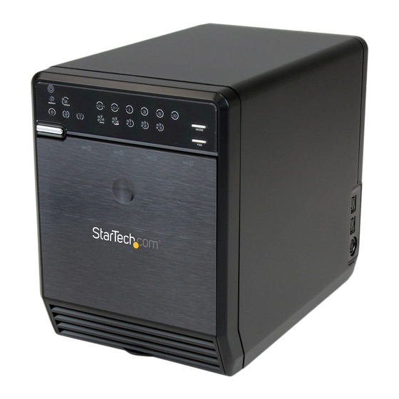
Page 1: Drive Enclosure
S354UFER Instruction Manual External Multi Bay Hard Drive Enclosure 3.5” 4 Drive eSATA USB FireWire External Multi Bay Hard Drive Enclosure with RAID Manual Revision:08/05/2010 For the most up-to-date information, please visit www.startech.com... -
Page 2: Fcc Compliance Statement
StarTech.com. Where they occur these references are for illustrative purposes only and do not represent an endorsement of a product or service by StarTech.com, or an endorsement of the product(s) to which this manual applies by the third-party company in question. -
Page 3: Table Of Contents
Table of Contents Introduction ..............1 Packaging Contents..............1 System Requirements ..............1 Installation ............... 2 Hardware Installation ..............4 Driver Installation .................5 How to Use ..............6 Hard Drive DIP Switch ..............6 RAID Mode ..................6 Drive Status Indicators ..............8 eSATA/USB/FireWire Connectivity ..........8 Fan Speed Control ..............9 Troubleshooting .............. -
Page 4: Introduction
Introduction StarTech.com’s S354UFER External Multi Bay Enclosure is a high- performance 4-drive SATA enclosure that connects to host systems through eSATA or USB or FireWire. Packaging Contents • 1 x S354UFER enclosure • 1 x Screw driver and screw kit •... -
Page 5: Installation
Installation Front View Drive Status LEDs RAID Mode LEDs Power LED Mode switch Fan Mode/Speed LEDs Interface LEDs Fan switch Drive Power/ Power Activity LEDs button Front Door release Rear View Cooling Fan (removable) Confirmation eSATA port button USB port DIP Switch 6-pin FireWire... - Page 6 Side View 9-pin FireWire ports DIN power connector...
-
Page 7: Hardware Installation
Hardware Installation 1. Secure the included Hard Drive Handles to the hard drives with the supplied screws and screw driver. 2. Press the front door in to release the latch and open the door. The door is also removable for easier access. 3. -
Page 8: Driver Installation
4. Remove the cardboard inserts (if first time setup) and then insert the hard drives into the slots. If installing less than 4 drives, ensure a drive is installed in the bottom slot. This will help when reinstalling the metal cage. Hard drives can be removed from the enclosure by pressing down on the handles, then pulling them out. -
Page 9: How To Use
How to Use Hard Drive DIP Switch The DIP switches on the rear of the hard drive enclosure first needs to be set, depending on the number of installed hard drives in the enclosure. The number of hard drives affects the available RAID modes that can be selected. - Page 10 Status Description SPAN: Spanning concatenates multiple hard drives into a single large disk. Provides no performance or redundancy benefits. RAID 0 (Stripe): Striping combines multiple disk into a single large disk array. The data is split evenly across each disk simultaneously. Read/ write performance is increased as a result, but failure of any one disk will make the entire array unusable.
-
Page 11: Drive Status Indicators
Drive Status Indicators Status Description An error has been detected on one or more hard drive. RAID array is currently rebuilding. eSATA/USB/FireWire Connectivity The LED indicators will show which host interface is currently active on the enclosure. To switch interfaces, shut the enclosure off and disconnect old cable and then connect the new cable and turn the enclosure back on. -
Page 12: Fan Speed Control
Fan Speed Control The cooling Smart Fan is automatically controlled by an integrated thermal sensor, but can also be set manually. The fan is capable of running at 3 different speeds depending on the temperature range of the enclosure (less than 45 C, between 45-54 C, and greater than C), or set manually to run constantly at a single speed. -
Page 13: Specifications
Specifications USB 2.0, SATA 3.0 Gb/s, Bus Interface FireWire800 1 x USB type B 1 x eSATA* External Connectors 1 x 6-pin FireWire 2 x 9-pin FireWire 1 x DIN power connector Chipset PLX OXUFS936QSE RAID Modes Span, 0, 1, 3, 5, 0+1 3 x Fan Speed 2 x Fan Mode 3 x Interface Link... - Page 14 Specifications - Continued Power Adapter 12VDC, 5A Dimensions 215.0mm x 126.0mm x 170.0mm Weight 1.8kg Windows 2000/XP/Server 2003/ Compatible Operating Vista, Mac OS 10.3 or later, Systems Linux * eSATA host controller requires Port Multiplier support...
-
Page 15: Technical Support
Limitation of Liability In no event shall the liability of StarTech.com Ltd. and StarTech.com USA LLP (or their officers, directors, employees or agents) for any damages (whether direct or indirect, special, punitive, incidental, consequential, or... - Page 16 StarTech.com has been making “hard-to-find easy” since 1985, providing high quality solutions to a diverse IT and A/V customer base that spans many channels, including government, education and industrial facilities to name just a few. We offer an unmatched selection of computer parts, cables, A/V products, KVM and Server...
Need help?
Do you have a question about the S354UFER and is the answer not in the manual?
Questions and answers