
Related Manuals for Clarke Start N charge BC100N


Summary of Contents for Clarke Start N charge BC100N
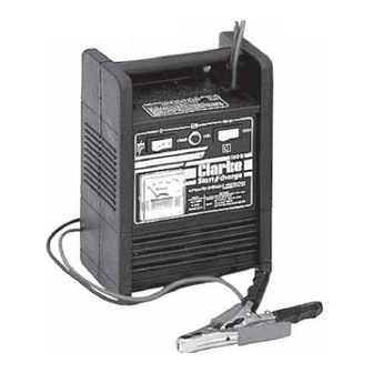
- Page 1 BATTERY/BOOSTER CHARGER BATTERY/BOOSTER CHARGER Model No: BC100N Part No: 6210101 OPERATING & MAINTENANCE INSTRUCTIONS 0906...
-
Page 2: Specifications
Weight ..............4Kg PARTS & SERVICE CONTACTS For Spare Parts and Service, please contact your nearest dealer, or CLARKE International, on one of the following numbers. PARTS & SERVICE TEL: 020 8988 7400 PARTS & SERVICE FAX: 020 8558 3622 e-mail as follows: PARTS: Parts@clarkeinternational.com... -
Page 3: Table Of Contents
Thank you for purchasing this CLARKE Battery Charger. Th1s units is designed for charging 12 Volt, lead acid battery and for providing a boost start in the event of a flat battery Before attempting to operate the charger, please read this instruction manual thoroughly, and follow all directions carefully. -
Page 4: Safety Precautions
IMPORTANT: SAFETY PRECAUTIONS PLEASE READ BEFORE USING THIS UNIT WARNING : Some electronic equipment can be damaged by boost charging or use of start facility. Check your vehicle handbook before using your Start ’N’ Charge. If in doubt consult the vehicle manufacturer. Nevertheless, you should not operate this equipment unless you are fully conversant with vehicle electrical systems, and battery charging techniques. -
Page 5: Electrical Connections
ELECTRICAL CONNECTIONS WARNING! THIS APPLIANCE IS DOUBLE INSULATED Connect the mains lead to a 230 volt (50Hz) domestic electrical supply via a standard 13 amp BS 1363 plug fitted with a 13 amp fuse, or a suitably fused isolator switch. IMPORTANT: The wires in the mains lead are coloured in accordance with the following code: Blue Neutral... -
Page 6: Procedure For Engine Starting
Fig.1 Procedure For Engine Starting. Check that the CHARGE/BOOST START switch (2) is in the OFF (O) position. Connect the appropriate output conductor to the unearthed battery terminal. Connect the other output conductor to the chassis, or engine bolt, away from the battery and fuel line Switch on the mains supply. -
Page 7: Procedure For Normal Charging
Procedure For Normal Charging (refer to Fig.1). Before charging or boosting ensure the battery terminals are clean and that the cells are filled with electrolyte to the correct level by adding distilled water where necessary. Where appropriate we recommend that the positive (-1-) lead (on the vehicle) to the battery is disconnected prior to charging. -
Page 8: Wiring Diagram
Wiring Diagram... -
Page 9: Parts Lists & Diagram
Parts Diagram Description Part No: Black Housing For Battery Chargers ....... . EM21690085 Welding Current Switch 16A 250V ........EM22200038 Thermic Switch 20A ............EM22210018 Switch 16A 250V ..............EM22200041 Rectifier 2 Diodes ............. . EM22400044 Clamp 60a ................ . EM22110003 Transformer Starter 230V .......... - Page 10 CLARKE Battery/Booster Chargers Other Battery Booster/Chargers in the comprehensive Clarke range include Model No: Max Charge Max Boost Boost Charge Thermal Dimensions Weight Part No: Amps Amps Volts Overload LxWxH - mm BC140 260x260x250 10.0 6210150 BC160 260x260x250 12.5 6210000...
Need help?
Do you have a question about the Start N charge BC100N and is the answer not in the manual?
Questions and answers